


POWER FEED 10M SINGLE/DUAL
OPERATION
BB-18 BB-18
Return to Section TOC Return to Section TOC Return to Section TOC Return to Section TOC
Return to Master TOC Return to Master TOC Return to Master TOC Return to Master TOC
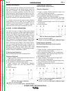
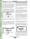
FEEDING ELECTRODE AND BRAKE
ADJUSTMENT
1) Turn the Reel or spool until the free end of the elec-
trode is accessible.
2) While tightly holding the electrode, cut off the bent
end and straighten the first 6" (150 mm). Cut off the
first 1" (25 mm). (If the electrode is not properly
straightened, it may not feed or may jam causing a
"birdnest".)
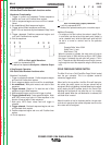
3) Insert the free end through the incoming guide
tube.
4) Press the Cold Inch key or the Cold Feed Mode gun
trigger and push the electrode into the drive roll.
When feeding with the gun trigger, unless “COLD
FEED” trigger mode is selected, the electrode and
drive mechanism are always “HOT” to work and
ground and could remain “HOT” several seconds
after the gun trigger is released.
___________________________________________
5) Feed the electrode through the gun.
6)
Adjust the brake tension with the thumbscrew on
the spindle hub, until the reel turns freely but with
little or no overrun when wire feeding is stopped.
Do not overtighten.
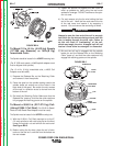
DRIVE ROLL PRESSURE SETTING
The Power Feed 10 Dual Wire Feeder pressure is fac-
tory pre-set to about position “2" as shown on the pres-
sure indicator on the front of the feedplate door. This
is an approximate setting.
The optimum drive roll pressure varies with type of
wire, surface condition, lubrication, and hardness. Too
much pressure could cause “birdnesting”, but too little
pressure could cause wire feed slippage with load
and/or acceleration. The optimum drive roll setting can
be determined as follows:
1) Press end of gun against a solid object that is elec-
trically isolated from the welder output and press
the gun trigger for several seconds.
2) If the wire "birdnests", jams, or breaks at the drive
roll, the drive roll pressure is too great. Back the
pressure setting out one turn, run new wire through
gun, and repeat above steps.
3) If the only result is drive roll slippage, disengage the
gun, pull the gun cable forward about 6" (150 mm).
There should be a slight waviness in the exposed
wire. If there is no waviness, the pressure is too
low. Increase the pressure setting one turn, recon-
nect the gun, tighten locking clamp and repeat the
above steps.
PROCEDURE FOR SETTING ANGLE
OF FEEDPLATE
1) Loosen the clamping collar screw using a 3/16"
Allen wrench. The clamping collar screw is
accessed from the bottom of the feedplate. It is the
screw which is perpendicular to the feeding direc-
tion.
2) Rotate feedplate to the desired angle and tighten
clamping collar screw.
GAS GUARD REGULATOR SETTING
1) With the gas supply shut off, the Gas Guard regu-
lator flow adjusting Key should be set to maximum
(full clockwise) which is rated to be 60 SCFH (28
l/min).
2) Adjust gas supply flow rate for a level higher than
will be required, then adjust Gas Guard flow adjust-
ing Key counterclockwise to the desired gas flow
rate.
WARNING