


POWER FEED 10M SINGLE/DUAL
OPERATION
B-8 B-8
Return to Section TOC Return to Section TOC Return to Section TOC Return to Section TOC
Return to Master TOC Return to Master TOC Return to Master TOC Return to Master TOC
• Limit setting for restricting the operators range of
control.
• Lockout to prevent unauthorized changes to
machine configuration.
Additionally, the MSP4 includes an infrared (IR) port for
wireless communication and configuration using a
Palm OS based hand held computer and a simplified
control layout.
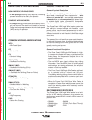
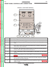
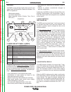
LAYOUT-CONTROLS
(SEE FIGURE B.3)
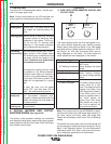
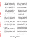
The MSP4 panel controls (Items 7 and 9) set consist of
an encoder knob Item 8 and two push buttons. The
encoder is primarily used to change the value of the
selected attribute.
The left pushbutton (Item 7)
is used to toggle between
Weld Mode selection and any active Arc Controls
(a.k.a. wave controls). The choices of wave controls
varies by weld mode. For example, weld mode 31 has
one wave control, “Pinch”. Weld mode 110 has three
wave controls, “Peak Current”, “Background Current”
and “Tailout”. If the selected weld mode has no wave
controls, pressing the left pushbutton will have no
affect. If the selected weld mode uses one or more
wave controls, pressing the left pushbutton will
sequence the selection from weld mode -> wave con-
trol 1 (if active) -> wave control 2 (if active) -> wave
control 3 (if active) -> wave control 4 (if active) then
back to weld mode.
The right pushbutton (Item 9)
is used to select attribut-
es that affect the available weld parameters such as
preflow time, burnback time, etc. Since most users will
require infrequent access to these attributes, they are
separate from weld mode selection and wave control
adjustment.
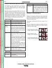
LAYOUT-DIGITAL DISPLAY
The MSP4 display consists of a large 4-digit, 7-seg-
ment LED display, two 8-character alphanumeric LED
displays and one 16-character alphanumeric LED dis-
play
. The information shown on the various displays
depends on the state of the user interface as described
below.
When the MSP4 is being used to select a weld mode,
the 4-digit display (Item 2) indicates the selected weld
mode number. The upper 8-character alphanumeric
display (Item 3) indicates the electrode type (steel, alu-
minum, etc.) The lower 8-character alphanumeric dis-
play (Item 4) indicates the electrode size (.035", 1/16",
etc.).
OVERVIEW:
The MSP4 is the standard mode select panel for the
Power Feed 10M Single Wire Feeder wire feeders. The
MSP4 is capable of:
- Weld mode selection.
- Arc Control adjustment.
- Weld sequence control (Preflow Time, Run-in
WFS, etc.)
3. MODE SELECT PANEL 4 (MSP4)
ITEM DESCRIPTION
1 IR (Infrared) Port.
2 Weld Mode Number.
3 Weld Wire Type.
4 Wire Size.
5 Weld Mode Description.
6
Status LED Lights-Weld Mode/Arc Control.
7 Selection Pushbutton Weld Mode or Arc
Control.
8
“Set” (Adjustment) Dial / Knob
9
Selection Pushbutton Start and End
Options.
10 Status LED Lights-Start/End Options.
START OPTIONS
END OPTIONS
SET
SETUP
IR PORT
PULSE 4043 Ar
3/64"
ALUMINUM
72
WELD MODE
ARC CONTROL
2
1
3
4
5
6
10
7
8
9
Through the use of alphanumeric displays, the MSP4
provides standard text messages designed to enhance
the user’s understanding of the machine’s operation as
well as provide advanced capabilities
The panel pro-
vides:
• Clear identification of the selected weld mode.
• Identification of weld modes not listed on the
preprinted weld mode list label.
• Control of up to four wave controls (arc controls.)
• Weld mode specific wave control name display
(Peak, Background, Pinch, etc.).
• Unit values are displayed (Amps, in/min, etc.).
• User-friendly machine setup and configuration.
FIGURE B.3