


Return to Section TOC Return to Section TOC Return to Section TOC Return to Section TOC
Return to Master TOC Return to Master TOC Return to Master TOC Return to Master TOC
OPERATION
B-5 B-5
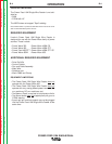
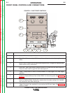
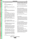
POWER FEED 10M SINGLE/DUAL
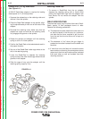
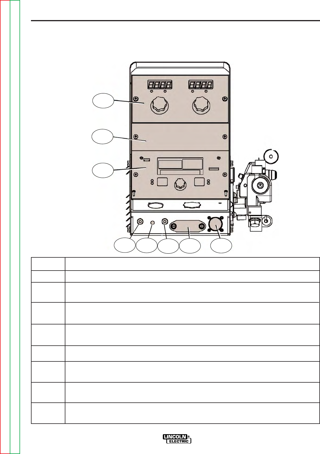
ITEM DESCRIPTION
1 Status LED indicates system status.
2
Digital Meter Display is a bright LED display of key welding information. Adjusting Parameter
Knobs.
3 MSP4 Panel is used to set the weld mode, adjust the arc, change arc start/end para-
meters and for set-up information.
4 Cold Feed - Gas Purge Switch, press the switch up to feed wire with weld output off.
Press the switch down for gas flow with weld output off.
5 2 step - 4 step Switch is used to choose between a 2 step trigger or a 4 step trigger
operation.
6
Location for Optional Memory Panel. (Order K2360-1 for the memory panel. See Accessories
Section).
7 Cover for Optional Water Cooling Kit, remove when the water cooling kit is installed.
See instructions with water cooling Kit.
8 Trigger Connector 5-pin amphenol for connecting the MIG gun trigger. See Installation
Section for detail.
2
6
3
5
1
4
7
8
FRONT PANEL CONTROLS AND CONNECTIONS
FIGURE B.1- CASE FRONT CONTROLS