


POWER FEED 10M SINGLE/DUAL
INSTALLATION
A-11 A-11
Return to Section TOC Return to Section TOC Return to Section TOC Return to Section TOC
Return to Master TOC Return to Master TOC Return to Master TOC Return to Master TOC
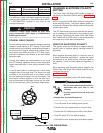
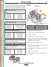
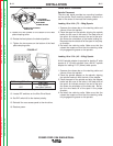
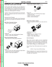
WIRE REEL LOADING
Spindle Placement
The wire reel stand provides two mounting locations
for the spindle. Each mounting location consists of a
tube in the center of the mast and locating slots.
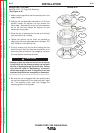
Loading 16 to 44 lb. (7.3 – 20kg) Spools
1. Squeeze the release bar on the retaining collar and
remove it from the spindle.
2. Place the spool on the spindle, aligning the spindle
brake pin with one of the holes in the back side of
the spool.
An indicator mark on the end of the spin-
dle shows the orientation of the brake holding pin.
Be certain the wire feeds off of the spool in the prop-
er direction.
3. Re-install the retaining collar. Make sure that the
release bar snaps out and that the retaining collar
fully engages the groove on the spindle.
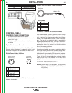
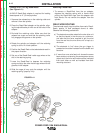
Loading 10 to 15 lb. (4.5 – 6.8kg) Spools
A K419 spindle adapter is required for loading 2" wide
spools on 2" (51mm) spindles. Use a K419-1 spindle
adapter for loading 2-1/2" (64mm) wide spools.
1. Squeeze the release bar on the retaining collar and
remove it from the spindle.
2. Place the spindle adapter on the spindle, aligning
the spindle brake pin with the hole in the adapter.
3. Place the spool on the spindle and align the adapter
brake tab with one of the holes in the back side of
the spool.
An indicator mark on the end of the spin-
dle shows the orientation of the brake tab. Be cer-
tain the wire feeds off of the spool in the proper
direction.
4. Re-install the retaining collar. Make sure that the
release bar snaps out and that the retaining collar
fully engages the groove on the spindle.
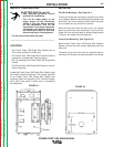
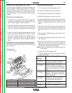
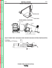
9. Loosen the two screws on the bottom of the feed
plate clamping collar.
10. Rotate the feed plate to the desired position.
11. Tighten the two screws on the bottom of the feed
plate clamping collar.
FIGURE A.7
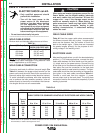
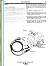
12. Remove the rear access panel on the wire drive.
13. Locate DIP switches on the Wire Drive Board.
14. Set DIP
switch #8 to the desired polarity.
15. Reinstall the rear access panel to the wire drive.
16. Restore power.
L
OW SPEED
SCREW SETTING
H
IGH SPEED
SCREW SETTING
SCREW FOR ROTATING
FEED PLATE
C
LAMPING COLLAR SCREWS
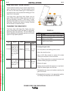
DIP Switch #8 Position
ON
OFF
Gear Ratio
High speed
Low speed (default)