


POWER FEED 10M SINGLE/DUAL
OPERATION
B-15 B-15
Return to Section TOC Return to Section TOC Return to Section TOC Return to Section TOC
Return to Master TOC Return to Master TOC Return to Master TOC Return to Master TOC
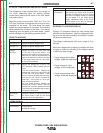
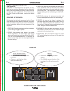
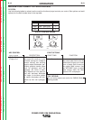
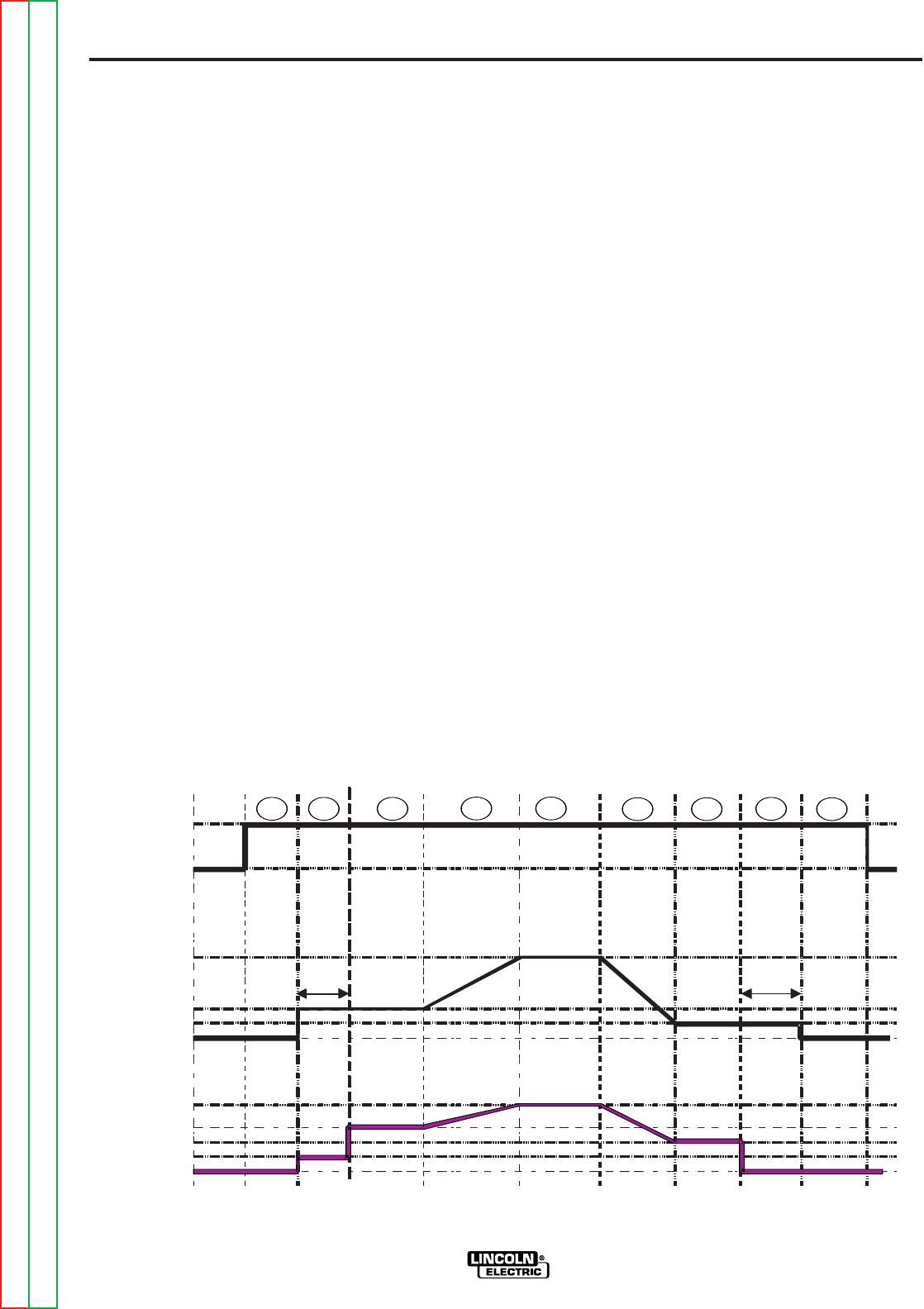
4 STEP TRIGGER OPERATION
(See Figure B.5)
The 4 step trigger sequence gives the most flexibility
when the Start, Crater and Burnback functions are
active. This is a popular choice when welding alu-
minum because extra heat may be needed during Start
and less heat desired during Crater. With 4 step trig-
ger, the welder chooses the amount of time to weld at
the Start, Weld and Crater settings by using the gun
trigger. Burnback reduces the likelihood of wire to
sticking in the weld pool at the end of a weld and also
prepares the end of the wire for the next arc start.
SEQUENCE OF OPERATION
Following is the total weld sequence that the Power
Feed 10M Single Wire Feeder will execute. If any para-
meter is inactive or its time is set to zero, the weld pro-
cedure immediately shifts to the next parameter in the
sequence.
1. PREFLOW
: Shielding gas begins to flow immediate-
ly when the gun trigger is pulled.
2. STRIKE: After preflow time expires, the power
source regulates to the start output and wire is
advanced towards the work piece at the Strike WFS.
If an arc is not established within 1.5 seconds, the
power source output and wire feed speed skips to
the weld settings.
3. START: The power source welds at the “Start” WFS
and voltage until the trigger is released.
4. UPSLOPE: Once the trigger is released, both the
machine output and the wire feed speed ramp up or
down to the weld settings throughout the start time.
The time period of ramping from the Start settings to
the Weld settings is called UPSLOPE.
5. WELD: After Upslope, the power source output and
the wire feed speed continue at the Weld settings.
6. DOWNSLOPE: Then as soon as the trigger is
pulled, the wire feed speed and power source output
ramp to the crater settings during the crater time.
The time period of ramping from the weld settings to
the crater settings is called DOWNSLOPE.
7. CRATER: Alter the Downslope time expires, the
machine welds at the Crater WFS and voltage set-
tings until ether the trigger is released or the Crater
time expires.
8. BURNBACK: After the crater time expires, the wire
feed speed is turned OFF and the machine output
continues for the burnback time.
9. POSTFLOW: Next, the machine output is turned
OFF and shielding gas continues to flow until the
post flow timer expires.
SShihieellddiingng
GaGass
IdleIdle PreflowPreflow
StrikeStrike
UpslopeUpslope
WWeldeld
BurnbackBurnback PostflowPostflow
IdleIdle
WFSWFS
OOnn
OOffff
SSttrriikkee
OOffff
WWeleldd
OOffff
WWeleldd
ArcArc EstablishedEstablished
TTriggerrigger
PulledPulled
TTriggerrigger
ReleasedReleased
1.5 sec1.5 sec
Max.Max.
BurnbackBurnback
TTimeime
SSttaarrtt
DownslopeDownslope
CCrrataterer
PPoweowerr
SSouourrccee
OutOutpputut
CCrrataterer
StartStart
TTriggerrigger PulledPulled
CraterCrater
TTriggerrigger ReleasedReleased
SSttarartt
22
11
33 44
55
66 77
88
99
FIGURE B.5