


POWER FEED 10M SINGLE/DUAL
OPERATION
BB-4 BB-4
Return to Section TOC Return to Section TOC Return to Section TOC Return to Section TOC
Return to Master TOC Return to Master TOC Return to Master TOC Return to Master TOC
FIGURE BB.1
OPERATIONAL FEATURES AND
CONTROLS
POWER FEED-10M SERIES SYSTEM CONFIGURATION
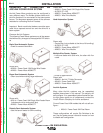
The specific system component function of the pc board will
be configurable by dip switch or by software configuration
tool. Dip switch configuration is as follows: Refer to DIP
switch settings of figures below.
Notes:
1. Basic Power Feed-10M systems consist of one User
Interface (UI), and up to two wire drives (a dual head wire
drive counts as two).
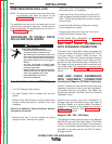
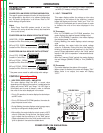
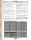
POWER FEED-10M DUAL BENCH DIP SWITCH SETTINGS
UI/WD PCB - S25629
(located on Wire Drive divider panel)
WD only PCB - S25616
(located on Wire Drive rear access door)
POWER FEED-10M DUAL BOOM DIP SWITCH SETTINGS*
UI only PCB - S25952
(located in Control Box)
WD only PCB #1 - S25616
(located on Wire Drive divider panel)
WD only PCB #2 - S25616
(located on Wire Drive rear access door)
* See power source manual for additional dip switch settings.
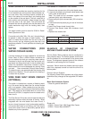
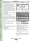
CONTROLS (Refer to Figure BB.2)
1. WIRE FEED SPEED (WFS) / AMP METER
This meter displays either the WFS or current value
depending on the status of the machine. Located below the
display are the text "WFS" and "Amps."
An LED light is
illuminated next to one of these in order to indicate
the units of the value displayed in the meter.
• Prior to CV operation, the meter displays the desired pre-
set WFS value.
• Prior to CC-Stick and CC-GTAW operation, the meter dis-
plays the preset current value.
• During Welding, the meter displays actual average amps,
but may be configured to display actual WFS.
• After welding, the meter holds the actual current or WFS
value for 5 seconds. During this time, the display is blink-
ing to indicate that the machine is in the "Hold" period.
Output adjustment while in the "Hold" period results in the
"prior to operation" characteristics stated above.
• After the 5 second "Hold" period, the meter displays the
set WFS (CV modes) or Amp (CC modes) value.
2. VOLT / TRIM METER
This meter displays either the voltage or trim value
depending on the status of the machine. Located
below the display are the text "Volts" and "Trim." An
LED light is illuminated next to one of these in order
to indicate the units of the value displayed in the
meter.
CV Processes
• Prior to CV-GMA
W and CV-FCAW operation, the
meter displays the desired preset Voltage value.
• Prior to CV-GMAW-P operation, the meter displays
the desired preset Trim value.
• During Welding, the meter displays actual average
volts.
• After welding, the meter holds the actual voltage
value for 5 seconds. During this time, the display is
blinking to indicate that the machine is in the "Hold"
period. Output adjustment while in the "Hold" period
results in the "prior to operation" characteristics stat-
ed above.
• After the 5 second "Hold" period, the meter displays
the set Voltage (GMAW, FCAW) or Trim (GMAW-P)
value.
CC Processes
• The meter displays the status of the output.
• When output is enabled, the meter will display "ON."
• When there is no output, the meter will display
"OFF."
START OPTIONS
END OPTIONS
SET
SETUP
IR PORT
PULSE 4043 Ar
3/64"
ALUMINUM
72
WELD MODE
ARC CONTROL
5
4
1 2 3 4 5 6 7 8
O
N
1 2 3 4 5 6 7 8
O
N
1 2 3 4 5 6 7 8
O
N
1 2 3 4 5 6 7 8
O
N
1 2 3 4 5 6 7 8
O
N