


POWER FEED 10M SINGLE/DUAL
OPERATION
B-14 B-14
Return to Section TOC Return to Section TOC Return to Section TOC Return to Section TOC
Return to Master TOC Return to Master TOC Return to Master TOC Return to Master TOC
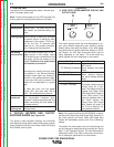
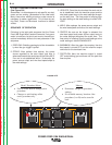
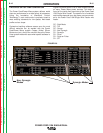
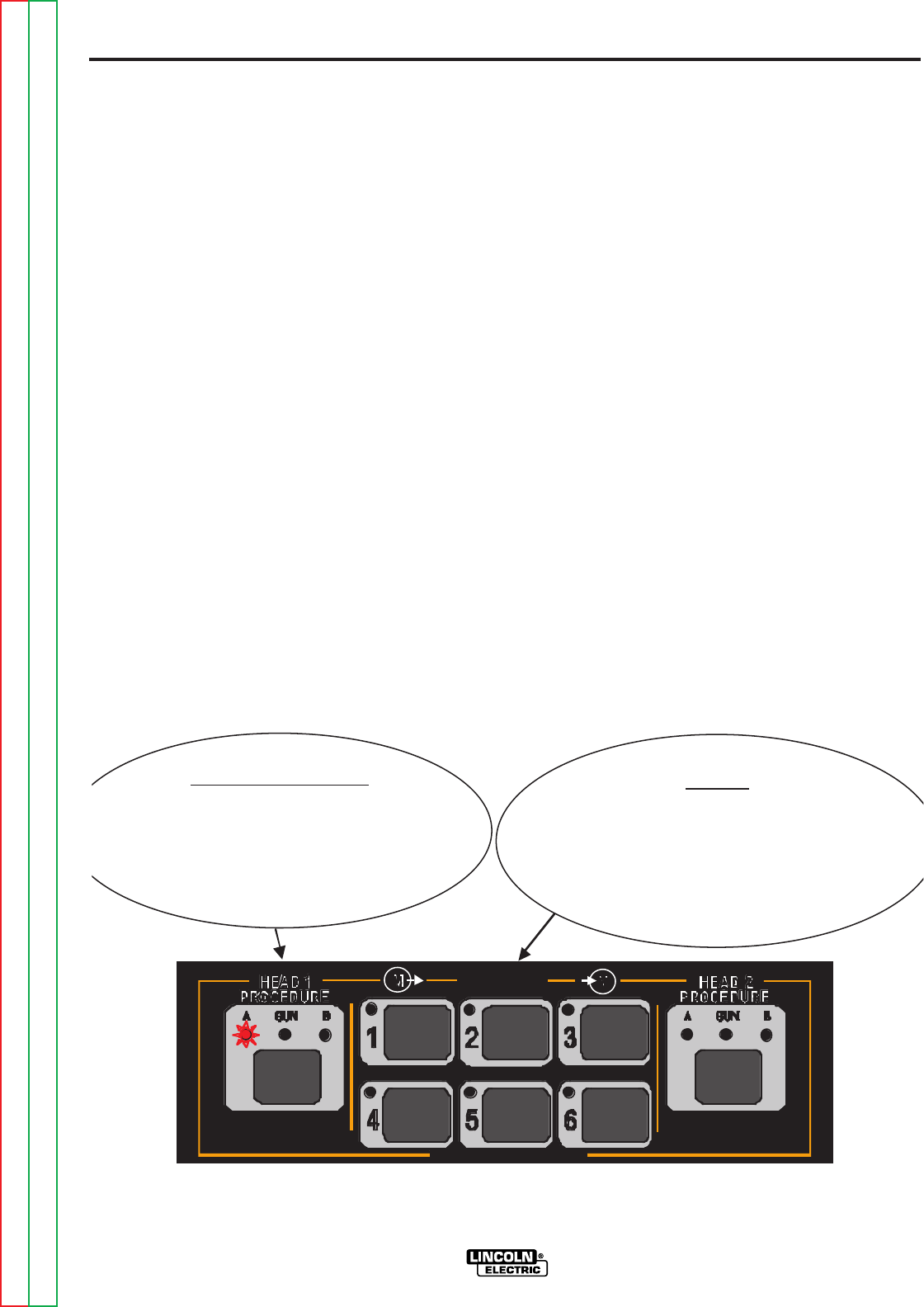
Head / Procedure Select
• Press to select head or change active
procedure.
• Changes to weld settings affect
active procedure only.
Ol d b ti t
Memory
• Permanent storage for procedure
settings.
• Six available memory locations. One
procedure (A or B) can be stored in
each.
PRESS AND HOLD TO SAVE
MEMORY
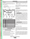
FIGURE B.4
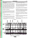
2 STEP TRIGGER OPERATION
(See Figure B.4)
Sometimes it is advantageous to set specific arc start,
crater and arc ending parameters for the ideal weld.
Many times when welding aluminum crater control is
necessary to make a good weld. This is done by set-
ting Start, Crater and Burnback functions to desired
values.
SEQUENCE OF OPERATION
Following is the total weld sequence that the Power
Feed 10M Single Wire Feeder will execute. If any para-
meter is inactive or its time is set to zero, the weld pro-
cedure immediately shifts to the next parameter in the
sequence.
1. PREFLOW: Shielding gas begins to flow immediate-
ly when the gun trigger is pulled.
2. STRIKE: After preflow time expires, the power
source regulates to the start output and wire is
advanced towards the work piece at the Strike WFS.
If an arc is not established within 1.5 seconds, the
power source output and wire feed speed skips to
the weld settings.
3. UPSLOPE: Once the wire touches the work and an
arc is established, both the machine output and the
wire feed speed ramp to the weld settings through-
out the start time. The time period of ramping from
the start settings to the weld settings is called UPS-
LOPE.
4. WELD: After upslope, the power source output and
the wire feed speed continue at the weld settings.
5. CRATER: As soon as the trigger is released, the
wire feed speed and power source output ramp to
the crater settings throughout the crater time. The
time period of ramping from the weld settings to the
crater settings is called DOWNSLOPE.
6. BURNBACK: After the crater time expires, the wire
feed speed is turned OFF and the machine output
continues for the burnback time.
7. POSTFLOW: Next, the machine output is turned
OFF and shielding gas continues until the post flow
timer expires.