


POWER FEED 10M SINGLE/DUAL
OPERATION
BB-15 BB-15
Return to Section TOC Return to Section TOC Return to Section TOC Return to Section TOC
Return to Master TOC Return to Master TOC Return to Master TOC Return to Master TOC
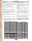
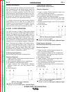
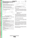
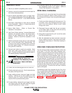
4 Step Synergic Operation:
Without Start/Crater/Burnback functions active
Waveform Functionality:
1. Trigger is pulled and released; Preflow sequence
begins and runs until Preflow timer expires.
2. Run-In sequence begins and runs until
Arc is estab-
lished
3. Arc established; Weld sequence begins.
4. Trigger pulled; Weld sequence continues.
Note: This can be done anytime between Step 3 and
5.
5. Trigger released; Postflow sequence begins and
runs until Postflow timer expires.
6. End of sequence.
WFS vs. Work point Waveform
= solid line represents WFS
---=
dashed line represents Work point or Machine Output
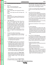
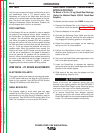
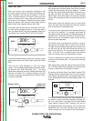
4 Step Synergic Operation:
With Start/Crater/Burnback functions active
Waveform Functionality:
1. Trigger is pulled and released; Preflow sequence begins
and runs until Preflow timer expires.
2. Run-In sequence begins and runs until Arc is established.
3. Arc established; Work point moves to set value in Start
sequence.
4. T
rigger released; Step 4 to 5 is start time set in Start
sequence to get to Weld sequence.
5. Weld sequence begins and runs until trigger is pulled.
6. Trigger pulled and held; Crater sequence begins. Work
point, WFS move to set value in Crater sequence in the
amount of time set within Crater sequence.
7.
Work point, WFS Crater values held until trigger is
released.
8. Trigger released; Burnback sequence begins and runs
until Burnback timer expires.
9. Postflow sequence begins and runs until Postflow timer
expires.
10. End of sequence.
1 2 3 4 5 6
WFS vs. Work point (Output) Waveform
= solid line represents WFS
--- = dashed line represents work point or machine output
Additional Comments:
• To achieve a Hot Start routine, the values in step 2 (Run-
In and Strike) can be set such that work point (output) is
set to a desired level, while the Weld work point level will
be set to a normal or nominal level for the particular
process.
Example Strike Value: 350A
Strike Time: 0.1 sec.
Weld Value: 170A
When the process is initiated, the work point will jump to
Strike work point of 350A with the set Run-In WFS. When
the trigger is released, the work point will jump to 170A in
the 0.1 seconds and the Weld sequence will begin, travers-
ing through the rest of the sequence using the functions set
forth.
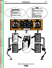
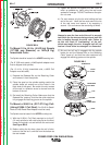
COLD FEED/GAS PURGE SWITCH
The Wire Drive has a Cold Feed/Gas Purge Switch located
near the gun connector. This is an up/down center-off
momentary toggle switch.
When held in the up position, the Wire Drive will feed wire,
but neither the power source nor the gas solenoid will be
energized. When cold feeding, the feed speed can be adjust-
ed by rotating the WFS encoder knob on the Control Box.
Adjusting the cold feed will not affect the run in or welding
wire feed speed. When the cold feed switch is released, the
cold feed value is saved.
When this switch is held in the down position, the gas sole-
noid valve is energized, but neither the power source nor the
drive motor will be energized.
1 2 3 4 5 6 7 8 910