


TROUBLESHOOTING & REPAIR
F-64 F-64
V205-T AC/DC
Return to Section TOC Return to Section TOC Return to Section TOC Return to Section TOC
Return to Master TOC Return to Master TOC Return to Master TOC Return to Master TOC
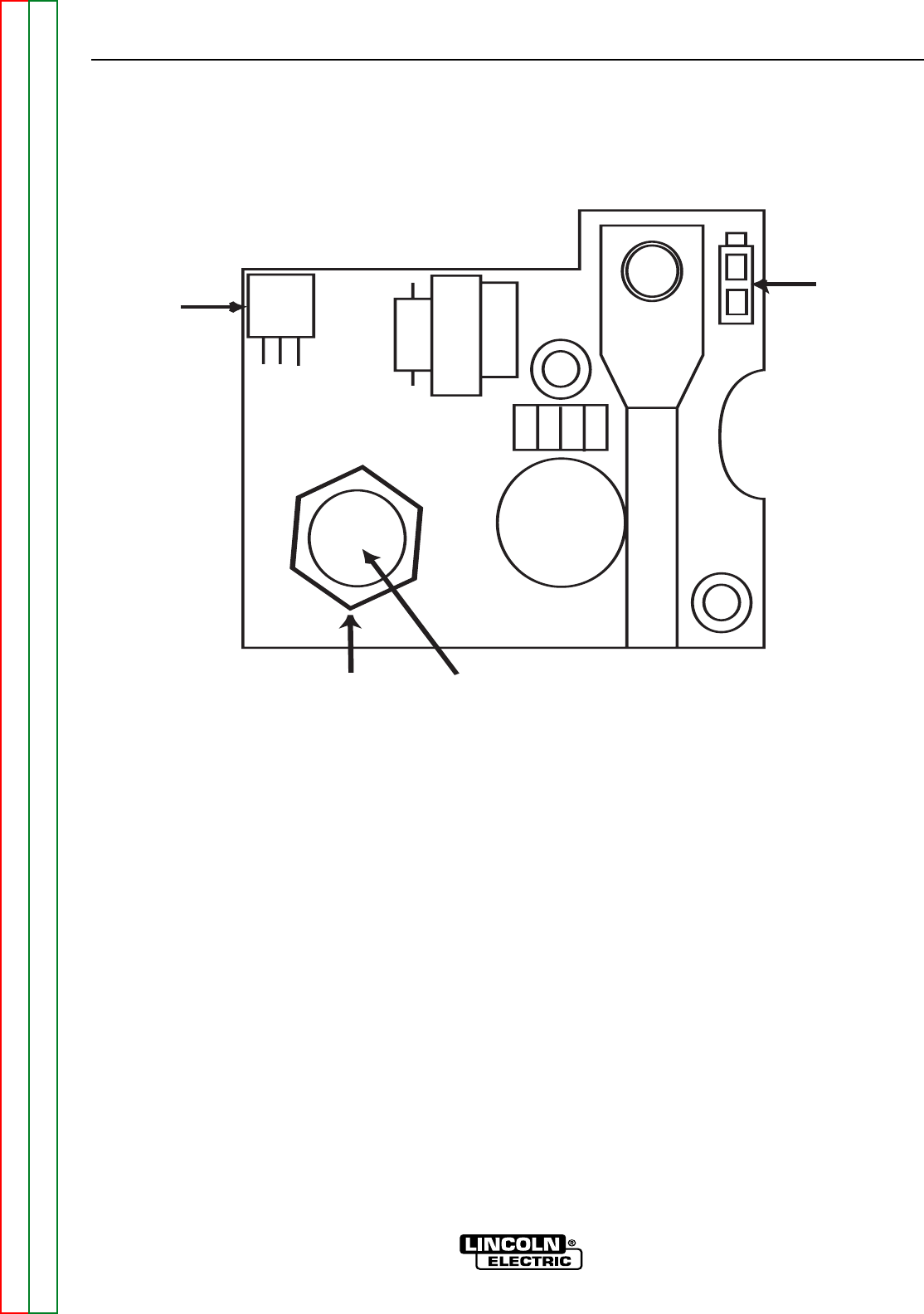
OUTPUT FILTER BOARD
REMOVAL AND REPLACEMENT (continued)
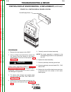
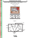
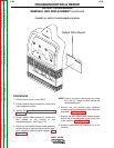
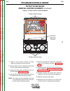
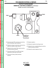
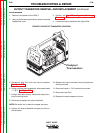
FIGURE F.34 OUTPUT FILTER BOARD
18. Reconnect lead CN7 previously removed from
the control/display board assembly.
19. Replace the large nut previously removed from
around the positive output terminal.
20. Replace the two output filter board mounting
screws previously removed.
21. Reconnect plugs CN1 and CN2 previously
removed from the output filter board.
22. Reconnect all heavy leads previously
removed.
23. Replace casefront.
24. Replace all casefront mounting screws.
25. Replace the four nameplate/keypad mounting
screws previously removed.
26. Replace the case wraparound cover.
-
+
CN1
CN2
Positive
Output
Terminal
Nut