


A-5 A-5
V205-T AC/DC
Return to Section TOC Return to Section TOC Return to Section TOC Return to Section TOC
Return to Master TOC Return to Master TOC Return to Master TOC Return to Master TOC
In all cases, the green or green/yellow grounding wire
must be connected to the grounding pin of the plug, usu-
ally identified by a green screw.
Attachment plugs must comply with the Standard for
Attachment Plugs and Receptacles, UL498.
The product is considered acceptable for use only when
an attachment plug as specified is properly attached to
the supply cord.
For use on engine drives, keep in mind the above input
draw restrictions and the following precaution.
ENGINE DRIVEN GENERATOR
The Invertec V205-T AC/DC can be operated on
engine driven generators as long as the 230 volt auxil-
iary meets the following conditions:
• The AC waveform peak voltage is below 400 volts.
• The AC waveform frequency is between 45 and
65Hz.
The following Lincoln engine drives meet these condi-
tions when run in the high idle mode:
• Ranger 250,305
• Commander 300, 400, & 500
Some engine drives do not meet these conditions (e.g.
Miller Bobcats, etc). Operation of the Invertec V205-T
AC/DC is not recommended on engine drives not con-
forming to these conditions. Such drives may deliver
unacceptably high voltage levels to the Invertec V205-
T AC/DC power source.
230V INPUT
The equipment is provided with a 230/115V cable,
6.6ft.(2m) in length with a 230V 6-50P attachment plug.
The Invertec V205-T AC/DC performs best when con-
nected to 230VAC inputs. This input allows full output
of the machine (200 amps).
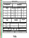
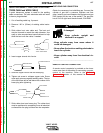
115V INPUT
A suitable 115V attachment plug must be installed on the
power cord to use the V205-T AC/DC with a 115V input
supply. The rated output of the V205-T AC/DC is available
when connected to a 30A branch circuit. When connected
to a branch circuit with lower amp rating, lower welding
current and duty cycle must be used. An output guide is
provided below. The values are approximate and must be
adjusted downward if the fuse or circuit breaker trips off.
Other loads on the circuit and fuse/circuit breaker charac-
teristics will affect the available output. Do not exceed
these welding conditions:
15A
branch circuit
10% duty cycle
Stick: 75A
TIG: 105A
20A branch circuit
10% duty cycle
Stick: 90A
TIG: 130A
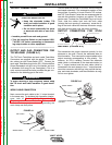
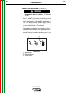
ATTACHMENT PLUG INSTALLATION
Connect the white (neutral) wire under terminal clamp
with silver screw, and black (hot) wire under terminal
clamp with brass screw. Connect green wire under ter-
minal clamp with green screw.
Failure to wire as instructed may cause personal
injury or damage to equipment. To be installed or
checked by an electrician or qualified person only.
---------------------------------------------------------------------------
WARNING
INSTALLATION