


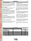
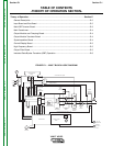
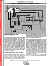
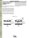
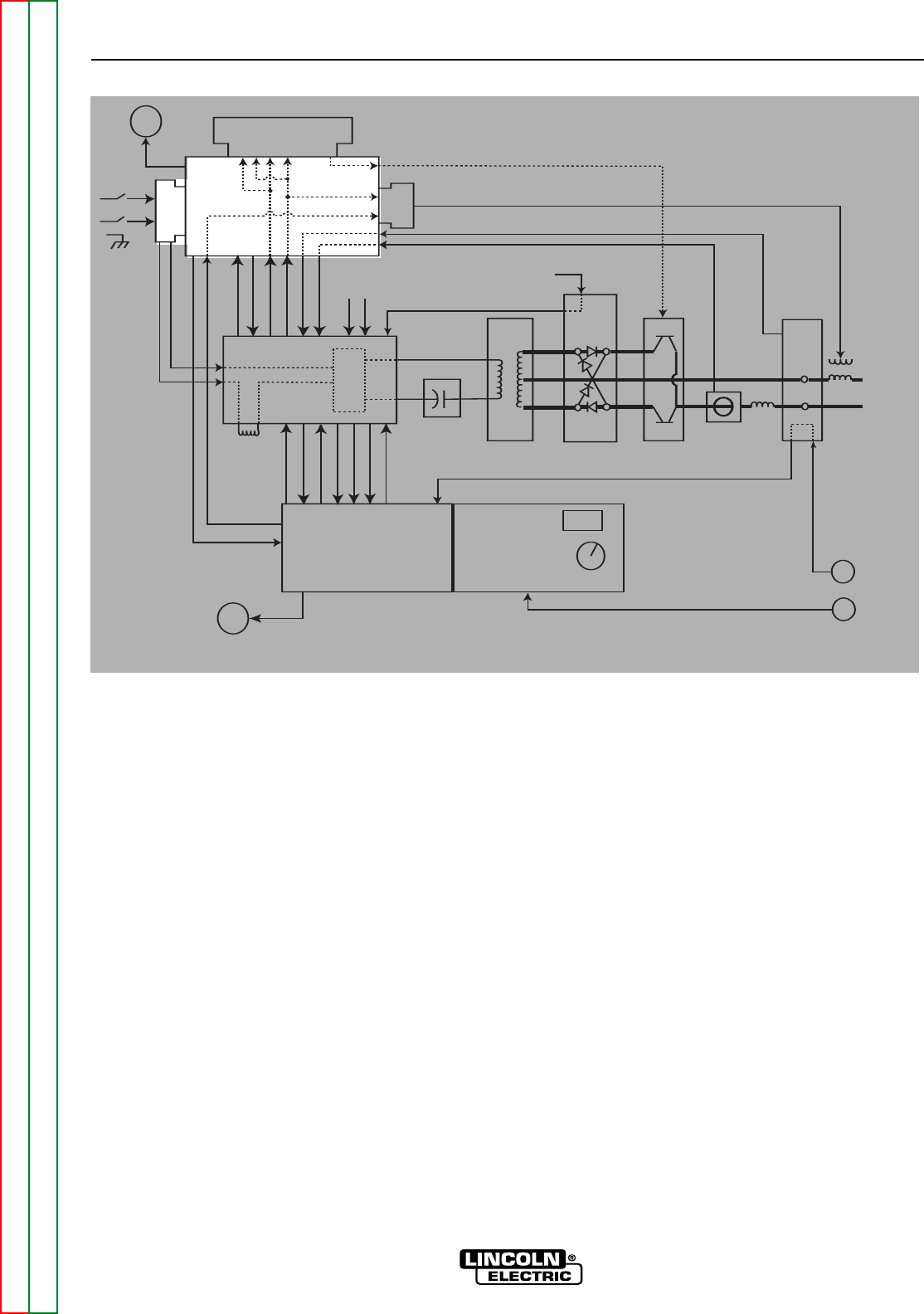
FIGURE E.2 – GENERAL DESCRIPTION, INPUT BOARD & BUS BOARD
Superimposition
board
Bus board
Fan
Input
board
HF
board
Main IGBT
& Power board
4
IGBT’s
Control board
Display & LED
board
888
Control
Knob
Gas
Solenoid
DC blocking
capacitor board
Main
Transformer
Output
board
Output
Transistor
Module
Current
Hall
Device
Output
Filter bd.
(bypass)
(D + E)
Remote 2/4
Remote
75, 76, 77
A, B, C
24 VDC Remote 2/4 path (D + E)
turn on AC ckt.
+15, -15, +5
input volt meter
thermostat info
set info
input current meter
turn on PWM
HF control signal
+48, +24
Input
Choke
_
+
RF coil
-48, +24,+15,-15,+5
reconnect info.
voltage feedback
high volt supply
turn on AC ckt.
current feedback
IGBT
Thermostats
Output
Diode
Thermostat
Voltage Feedback
Current Feedback
AC DC Gate drive signals
24 VDC
48 VDC
Output
Choke
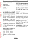
GENERAL DESCRIPTION
The Invertec V205T AC/DC is an inverter based indus-
trial welding power source that utilizes single-phase
input power to produce constant current AC or DC
output for both Stick (SMAW) and TIG (GTAW). With
230VAC input applied the V205T is rated at 200 amps,
18volts at a 40% duty cycle. With 115VAC applied the
machine is rated at 150 amps, 16 volts at a 40% duty
cycle. The machine has the capabilities to produce
several varieties of AC waveforms (square, sinusoidal
and triangular). The unit also employs an auto recon-
nect feature that does not require manual intervention
when the input power is changed from 115VAC to
230VAC or 230VAC to 115VAC. When in the TIG mode
the operator may select to use either the high frequen-
cy or touch start function.
INPUT BOARD AND BUS BOARD
The single phase input voltage is applied to the V205T
through a line switch located on the back of the
machine. The AC input voltage is filtered and condi-
tioned by a network of inductors, capacitors and a
varistor that are all located on the Input Board. This fil-
tered input voltage is applied to the Main IGBT Inverter
Board. Another function of the Input Board is to pre-
vent high frequency inverter generated “noise” from
being induced back into the supply lines.
The Bus Board performs several functions within the
V205T. It accepts and distributes power and informa-
tion to other circuitry. This interfacing is accomplished
through harness and ribbon connectors and also via
other PC boards that are plugged directly into the Bus
Board. The Input Board, the High Frequency Board
and the AC Super-Imposition Board plug into the Bus
Board. Circuitry located on the Main IGBT Inverter
Board, the Control Board, the Output Module Board,
the Output Filter Board and the Hall Effect Device
interface with the Bus Board. Some circuits are also
incorporated within the Bus Board. They are the fan
circuit (24VDC) and an input voltage sensing circuit
that is utilized by the auto reconnect circuitry located
on the Main Inverter Board.
The fan fuse F3, the 400VDC fuse F2 and the water
cooler F1 (not used) are also located on the Bus Board.
THEORY OF OPERATION
E-2 E-2
V205-T AC/DC
Return to Section TOC Return to Section TOC Return to Section TOC Return to Section TOC
Return to Master TOC Return to Master TOC Return to Master TOC Return to Master TOC
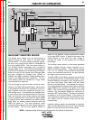
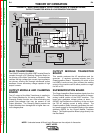
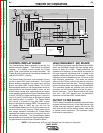
NOTE: Unshaded areas of Block Logic Diagram are the subject of discussion.