


A-6 A-6
V205-T AC/DC
Return to Section TOC Return to Section TOC Return to Section TOC Return to Section TOC
Return to Master TOC Return to Master TOC Return to Master TOC Return to Master TOC
INSTALLATION
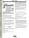
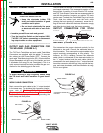
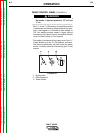
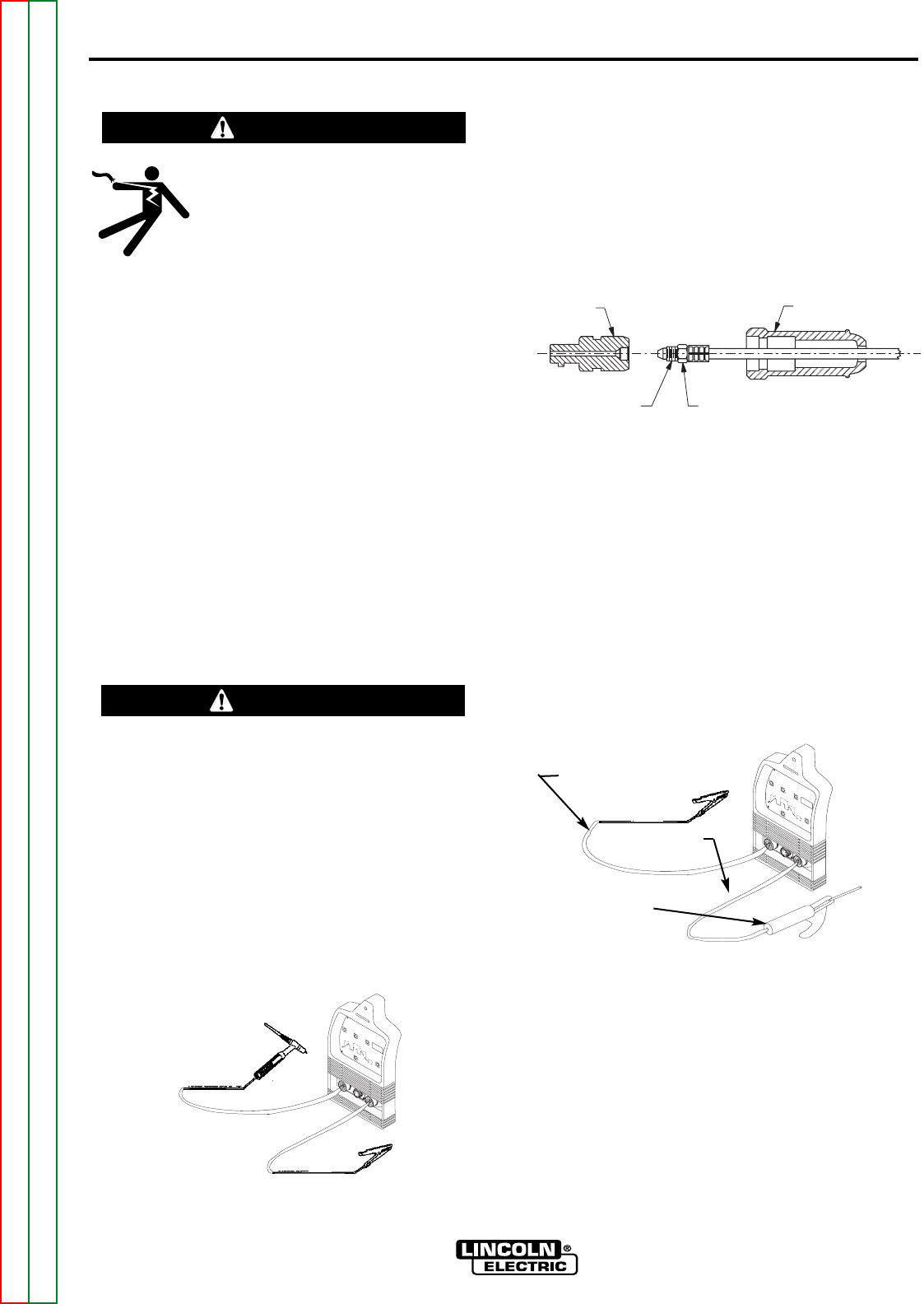
OUTPUT AND GAS CONNECTION FOR
TIG WELDING (FIGURE A.1)
The TIG Torch Twist-Mate and work cable Twist-Mate
Connectors are supplied with the welder. To connect
the cables, turn the Power Switch “OFF”.
Connect the
torch cable Twist-Mate plug into the DC(-)
Electrode/Gas
Output Receptacle on the front of the welder and turn
it clockwise until snug,(Do not Overtighten). This is a
quick connect terminal and also provides the gas con-
nection for the shielding gas to the torch.
To avoid receiving a high frequency shock, keep
the TIG torch and cable insulation in good condi-
tion.
___________________________________________
WORK CABLE CONNECTION
Next, connect the work cable to the “+” output terminal
in the same way. To minimize high frequency interfer-
ence, refer to Machine Grounding and High
Frequency Interference Protection section of this
manual for the proper procedure on grounding the
work clamp and work piece.
OUTPUT CONNECTIONS
ELECTRIC SHOCK can kill.
• Keep the electrode holder, TIG
torch and cable insulation in good
condition and in place.
• Do not touch electrically live parts
or electrode with skin or wet cloth-
ing.
• Insulate yourself from work and ground.
• Turn the input line Switch on the Invertec V205-
T AC/DC “off” before connecting or disconnect-
ing output cables or other equipment.
-----------------------------------------------------------
WARNING
+
-
WORK CLAMP
WORK CABLE
TIG TORCH
WARNING
FIGURE A.1
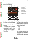
This unit does not include a TIG torch, but one may be
purchased separately. The accessories section of this
manual lists a number of Lincoln Electric TIG torches,
and TIG Torch Starter Packs that are recommended for
use with this machine; however, any similar TIG torch
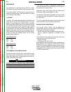
can be used. To attach the Twist-Mate Plug to a Lincoln
Torch, slide the rubber boot onto the torch cable
(enlarge the boot opening if necessary), screw the fit-
ting on the torch cable into the brass connector snugly
and slide the boot back over the brass connector.
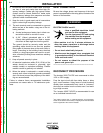
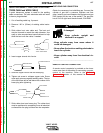
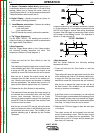
OUTPUT CONNECTION FOR STICK
WELDING (FIGURE A.2)
First determine the proper electrode polarity for the
electrode to be used. Consult the electrode data for
this information. Then connect the output cables to the
output terminals corresponding to this polarity. For
instance, for DC(+) welding, connect the electrode
cable (which is connected to the electrode holder) to
the “+” output terminal and the work cable (which is
connected to the work clamp) to the “-” output terminal.
Insert the connector with the key lining up with the key-
way, and rotate clockwise; until the connection is snug.
Do not over tighten.
TIG ADAPTER
RETAINING COMPOUND
STRAIN RELIEF BOOT
TIG TORCH POWER CABLE WITH GAS FITING
+
-
FIGURE A.2
WORK CABLE
WORK CABLE
STICK ELECTRODE
HOLDER