


V205-T AC/DC
Return to Section TOC Return to Section TOC Return to Section TOC Return to Section TOC
Return to Master TOC Return to Master TOC Return to Master TOC Return to Master TOC
TROUBLESHOOTING & REPAIR
F-66 F-66
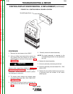
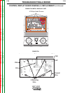
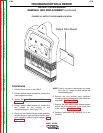
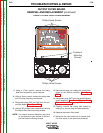
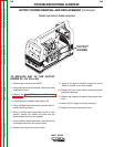
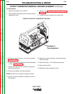
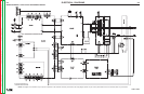
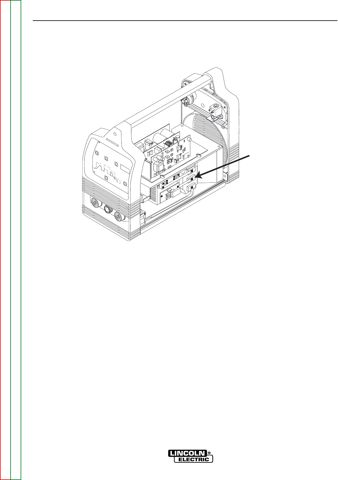
FIGURE F.35 OUTPUT DIODE LOCATION
OUTPUT
DIODES
OUTPUT DIODES REMOVAL AND REPLACEMENT (continued)
TO REPLACE ANY OF THE OUTPUT
DIODES (D1, D2, D3 or D4)
1. Remove input power to the V205-T.
2. Using a phillips head screwdriver, remove the case
wraparound cover.
3. Perform the Input Filter Capacitor Discharge
Procedure detailed earlier in this section.
4. Locate the output diodes. See Figure F.35.
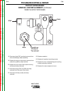
5. Using a phillips head screwdriver, remove the P.C.
board mounting screws.
6. Using a phillips head screwdriver and/or a 7mm
wrench, remove the copper bus bars from the
diode module that is to be replaced.
7. Using a phillips head screwdriver, remove the two
mounting screws from the output diode.
8. Remove and replace the output diode.
9. Apply a thin layer of heatsink compound to the
areas of contact on the new diode/s.
10. Replace the two output diode mounting screws
previously removed.
11. Replace the copper bus bars to their proper loca-
tions.
12. Mount the P.C. board previously removed.
13. Replace the case wraparound cover.