


Return to Section TOC Return to Section TOC Return to Section TOC Return to Section TOC
Return to Master TOC Return to Master TOC Return to Master TOC Return to Master TOC
TROUBLESHOOTING & REPAIR
F-17 F-17
V205-T AC/DC
INPUT FILTER BOARD TEST (continued)
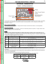
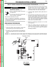
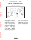
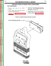
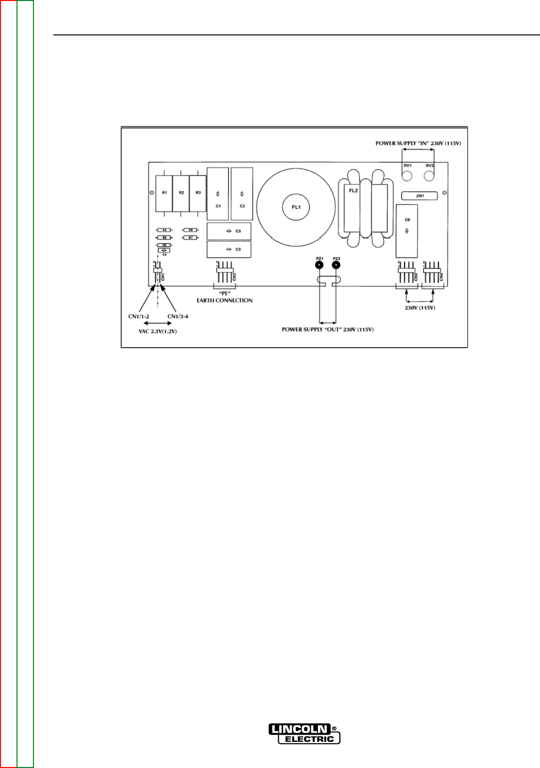
FIGURE F.5 INPUT FILTER BOARD
Note 1: A varistor ZN1 is placed between the two
power supply phases, so if an instantaneous
voltage in excess of 275VAC appears on ter-
minals RV1 & RV2, the varistor very rapidly
becomes conductive and thus absorbing a
current peak sufficient to limit the above said
overvoltage; this way the varistor ZN1 pro-
tects the other parts of the machine from
energy-limited overvoltages. This process has
no destructive effect on the component if the
energy generated by the voltage peak is low,
as in the case of atmospheric lightening
strikes. However, if over-voltage is high and
prolonged, the varistor cannot dissipate this
high energy and fails. For example, the
machine is improperly connected to 275VAC,
or the over-voltage is caused by non stabilized
power units of inadequate capacity.
Note 2: The radio noise suppression circuit has two
purposes: to keep the machine’s radio fre-
quency emisions within limits specified by
standards and to ensure the machine’s immu-
nity against the same type of problems
caused any electronic devices connected to
the same power supply source. The filter con-
sists of a network of capacitors, some of
which are grounded, and a toroidal inductor.