


TROUBLESHOOTING & REPAIR
F-63 F-63
V205-T AC/DC
Return to Section TOC Return to Section TOC Return to Section TOC Return to Section TOC
Return to Master TOC Return to Master TOC Return to Master TOC Return to Master TOC
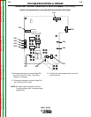
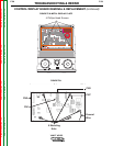
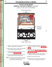
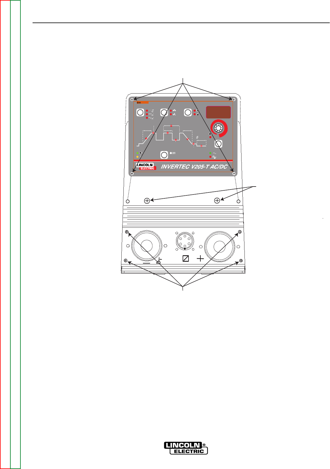
FIGURE F.33 CASE FRONT SCREW REMOVAL
Phillips Head Screws
®
PARAMETER
SELECT / HOLD
PULSE ON
UPSLOPE
% ON TIME
DOWNSLOPE
FINISH
CURRENT
BACKGROUND
CURRENT
POSTFLOW
WELD
CURRENT
sec
sec
sec
MODE
STICK
DC TIG
AC TI G
WARNING
TRIGGER
4-STEP
2-STEP
LOCAL
REMOTE
OUTPUT
A
PULSE FREQUENCY
Hz
V
AC FREQUENCY Hz
AC BALANCE % EN
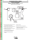
Phillips Head Screws
Casefront
Mounting
Screws
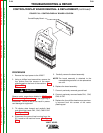
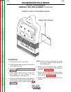
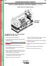
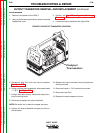
OUTPUT FILTER BOARD
REMOVAL AND REPLACEMENT (continued)
9. Using a 17mm wrench, remove the heavy
lead from the positive output terminal.
10. Using a 13mm wrench, remove the heavy lead
from the high frequency transformer.
11. Disconnect plugs CN1 and CN2 from the out-
put filter board. See Figure F.34.
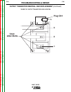
12. Using a 90
o
phillips head screwdriver, remove
the output filter board mounting screws.
NOTE: The output terminal assembly may have
to be removed to gain access to the out-
put filter board mounting screws.
13. Remove the large nut holding the output filter
board to the positive terminal. See Figure
F.34.
14. Disconnect plug CN7 from the control/display
board assembly. See Control/Display Board
Removal Procedure for plug CN7 location.
15. Carefully remove the output filter board by
sliding it by the the plug and lead assembly.
16. Replace the output filter board.
17. Maneuver the new board into its proper loca-
tion from which it was previously removed.