


Return to Section TOC Return to Section TOC Return to Section TOC Return to Section TOC
Return to Master TOC Return to Master TOC Return to Master TOC Return to Master TOC
V205-T AC/DC
TROUBLESHOOTING & REPAIR
F-50 F-50
PROCEDURE
1. Remove input power to the V205-T.
2. Using a phillips head screwdriver remove the case
wraparound cover.
3. Perform the Input Filter Capacitor Discharge
Procedure detailed earlier in this section.
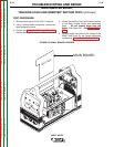
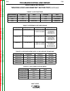
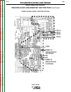
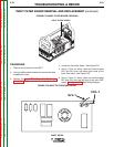
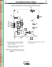
4. Locate the input filter board. See Figure F.24.
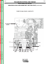
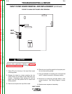
5. Using a 7mm nut driver, label and remove leads
R/L1 and S/L2 from the upper right corner of the
input filter board. See Figure F.25.
6. Using a 7mm nut driver, label and remove leads
RV1 and RV2 from the left side of the main IGBT
board. See Figure F.26. See Wiring Diagram
INPUT FILTER BOARD REMOVAL AND REPLACEMENT (continued)
S/L1
R/L1
FIGURE F.24 INPUT FILTER BOARD LOCATION
FIGURE F.25 INPUT FILTER BOARD LEADS
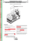
INPUT FILTER BOARD