


PROCEDURE
1. Remove input power to the V205-T.
2. Using a phillips head screwdriver, remove the case
wraparound cover.
3. Perform the Input Filter Capacitor Discharge
Procedure detailed earlier in this section.
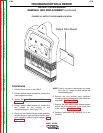
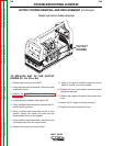
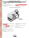
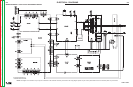
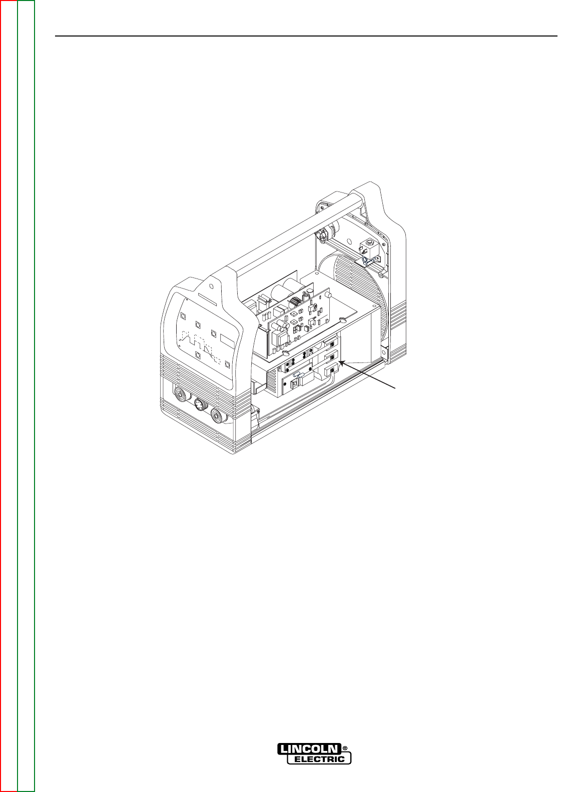
4. Locate the output transistor. See Figure F.36.
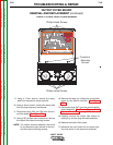
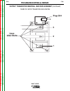
5. Disconnect plug CN1 from the output transistor.
See Figure F.37.
6. Using a phillips head screwdriver, disconnect leads
1, 2 & 3. See Figure F.37.
7. Using a 5mm allen wrench, remove the output tran-
sistor mounting bolts.
8. Remove and replace the output transistor.
NOTE: Be careful not to bend the copper bus bars.
9. Apply a thin layer of heatsink compound to all con-
tact surfaces.
10. Replace the output transistor mounting bolts pre-
viously removed.
11. Reconnect leads 1, 2 & 3 previously removed.
12. Reconnect lead CN1.
13. Replace the case wraparound cover.
TROUBLESHOOTING & REPAIR
F-68 F-68
V205-T AC/DC
Return to Section TOC Return to Section TOC Return to Section TOC Return to Section TOC
Return to Master TOC Return to Master TOC Return to Master TOC Return to Master TOC
OUTPUT TRANSISTOR REMOVAL AND REPLACEMENT (continued)
Output
Transistor
FIGURE F.36 OUTPUT TRANSISTOR LOCATION