


TROUBLESHOOTING & REPAIR
F-29 F-29
V205-T AC/DC
Return to Section TOC Return to Section TOC Return to Section TOC Return to Section TOC
Return to Master TOC Return to Master TOC Return to Master TOC Return to Master TOC
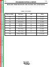
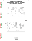
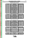
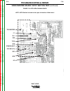
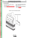
BUS BOARD TEST (continued)
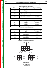
TABLE F.5 PLUG CN2 TEST POINTS
TABLE F.6 PLUG CN3 TEST POINTS
Wire #
21
22
23
24
26
27
28
29
30
32
Description
Thermal Trigger
Output Hall Probe
Hall Probe
Ground Gate Switch B
Ground Gate Switch A
Thermal Trigger (AC Unit)
Ground Hall Probe
Hall Probe
Gate Switch B
Gate Switch A
Expected Voltage
-------
-------
+15 VDC
-------
-------
-------
-------
-15 VDC
-------
-------
Wire #
61
65
63
64[-], 66[+]
Description
- Superimposition
Ground Superimposition
+ Superimposition
Welding Voltage
Expected Voltage
53.2 VDC
(1)
-------
53.2 VDC
(1)
52.6 VDC
TABLE F.7 PLUG CN4 TEST POINTS
Wire #
41
42
44
45
48
Description
Front Panel Supply
Front Panel Supply Ground
HF Start
Front Panel Supply
HF Start Ground
Expected Voltage
24 VDC
-------
-------
48 VDC
-------
TABLE F.8 PLUG CN7 TEST POINTS
TABLE F.9 PLUG CN1 TEST POINTS
Wire #
11
Earth Cable
12
Earth Cable
Description
Water Cooling Supply
Water Cooling Supply
Water Cooling Supply
-------
Expected Voltage
-------
-------
-------
-------
Wire #
5[+], 6[-]
Description
Fan
Expected Voltage
24 VDC
(1)
In TIG mode only when Remote is pushed, comes on for two sec. then goes to zero. In STICK mode is present all
the time.