


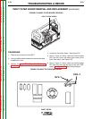

Observe static precautions detailed in PC Board
Troubleshooting Procedures at the beginning of this
section.
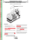
7. Clean RTV off of the top of the input filter board
mounting slides.
8. Release the board by simply pressing the two
metal buttons at the ends of the board with your
thumbs. Depressing these buttons will free the
plastic lock pins that prevent the P.C. board from
sliding upward.
9. Remove and replace the input filter board.
10. Slide the new input filter board into its proper posi-
tion on the mounting slides.
11. Push on backside of mounting pins to ensure that
the P.C. board is secured in its proper position.
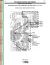
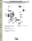
12. Reconnect all previously removed leads to their
proper locations. See Wiring Diagram if neces-
sary.
13. Replace case wraparound assembly.
CAUTION
V205-T AC/DC
Return to Section TOC Return to Section TOC Return to Section TOC Return to Section TOC
Return to Master TOC Return to Master TOC Return to Master TOC Return to Master TOC
TROUBLESHOOTING & REPAIR
F-51 F-51
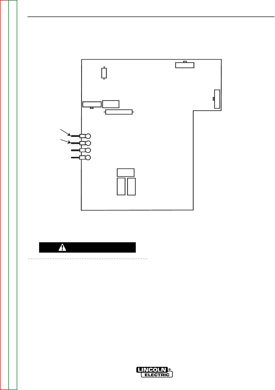
RV1
RV2
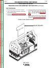
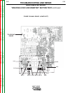
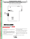
FIGURE F.26 MAIN IGBT BOARD LEAD REMOVAL
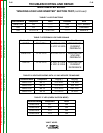
INPUT FILTER BOARD REMOVAL AND REPLACEMENT (continued)