


V205-T AC/DC
Return to Section TOC Return to Section TOC Return to Section TOC Return to Section TOC
Return to Master TOC Return to Master TOC Return to Master TOC Return to Master TOC
TROUBLESHOOTING & REPAIR
F-62 F-62
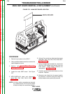
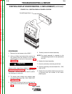
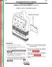
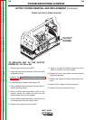
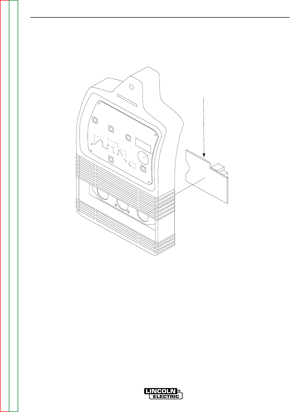
FIGURE F.32 OUTPUT FILTER BOARD LOCATION
Output Filter Board
OUTPUT FILTER BOARD
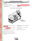
REMOVAL AND REPLACEMENT (continued)
PROCEDURE
1. Remove input power to the V205-T.
2. Using a phillips head screwdriver, remove the
case wraparound cover.
3. Perform the Input Filter Capacitor Discharge
Procedure detailed earlier in this section.
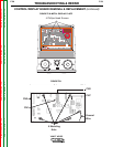
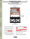
4. Using a phillips head screwdriver, remove the
four screws at the corners of the
nameplate/keypad. See Figure F.33.
5. Gently pull the Control/Display board assembly
forward and up to gain access to the two case-
front mounting screws located beneath. See
Figure F.33.
NOTE: There is no need to disconnect any leads
from the P.C. boards located behind the
nameplate/keypad.
6. Remove the two phillips head casefront
mounting screws located behind the metal dis-
play plate. See Figure F.33.
7. Remove the four phillips head screws located
around the output terminals on the lower front
of the machine. See Figure F.33.
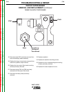
8. Carefully manipulate the casefront off of the
machine.