


TROUBLESHOOTING & REPAIR
F-9 F-9
V205-T AC/DC
Return to Section TOC Return to Section TOC Return to Section TOC Return to Section TOC
Return to Master TOC Return to Master TOC Return to Master TOC Return to Master TOC
EXTERNAL DIAGNOSTICS
®
PARAMETER
SELECT / HOLD
PULSE ON
UPSLOPE
% ON TIME
DOWNSLOPE
FINISH
CURRENT
BACKGROUND
CURRENT
POSTFLOW
WELD
CURRENT
sec
sec
sec
MODE
STICK
DC TIG
AC TI G
WARNING
TRIGGER
4-STEP
2-STEP
LOCAL
REMOTE
OUTPUT
A
PULSE FREQUENCY
Hz
V
AC FREQUENCY Hz
AC BALANCE % EN
Power Supply
Alarm
Display
Output Current Control
Output
Set-up Parameter
Select Button
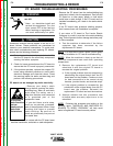
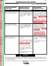
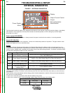
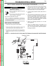
FIGURE F.1 EXTERNAL DIAGNOSTICS
The front panel controls the status of the equipment and shows it to the operator via the LED’s and the display. Immediately
after switch-on of the equipment, the front panel executes an autotest operation, all LED’s will light up and the display
shows”200” as a check.
Power supply LED (GREEN)
Indicates the machine switch-on status. Always present if the panel, and therefor the machine, is correctly powered.
Alarm LED (YELLOW)
Indicates a protection status of the equipment. Comes on to indicate the presence of a problem. The type of alarm is indi-
cated in the display by an error code (see below).
Display
Immediately after the autotest operations above, the display briefly shows the software version of control panel (e.g. 01).
It indicates the welding parameters requested by the operator (with the help of the other keys) and immediately after striking
of the arc sets to reading mode, providing the real value of the current delivered by generator. It indicates a protection status
via codes with simultaneous switch-on of the yellow LED.
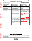
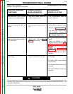
Indic.
E10
E11
E12
E13
E14
Type of Error
Internal Heatsink Overtemp.
Power Supply Overvoltage
Power Supply Undervoltage
Front Panel Memory Error
Front Panel Secondary
Memory Error
Action
Remove upper cover, check internal temperature, check thermal device status
(N.C.). See machine layout.
Remove upper cover, check that the power supply voltage is within the established
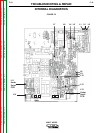
range (+/- 15%). Check reading voltage on 15.14.314 CN1 (See Fig. 9)
Remove upper cover, check that the power supply voltage is within the established
range (+/- 15%). Check reading voltage on 15.14.315 CN1 (See Fig. 9)
Remove upper cover, check front panel power supplies. Perform front panel reset*
test and replace if necessary.
Remove upper cover, check front panel power supplies. Perform front panel reset*
test and replace if necessary.
*Note: to reset front panel (memory) see procedure in “Set-up parameters” chapter below.
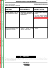
Normally, when cause(s) of alarm(s) is (are) removed, press one of the keys to exit from alarm status (or switch off and on
the machine).
Thermal alarm will be automatically reset by letting go down internal temperature: machine will execute a new autotest and
then start as in normal operation.
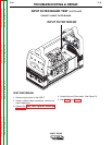
In case of error code E10, see also the three thermal switches in fig. below.
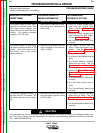
In case of error codes E11/E12, check input power supply voltage, with reference to the following table.
Under/Overvoltage alarm thresholds
Power supply rated
voltage
115 VAC
230 VAC
92 VAC
184 VAC
138 VAC
276 VAC
Overvoltage
Undervoltage