


Return to Section TOC Return to Section TOC Return to Section TOC Return to Section TOC
Return to Master TOC Return to Master TOC Return to Master TOC Return to Master TOC
TROUBLESHOOTING & REPAIR
F-32 F-32
V205-T AC/DC
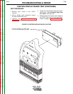
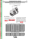
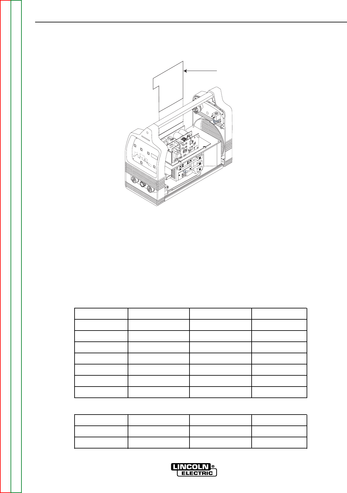
MAIN INVERTER BOARD “UPFR” SECTION TEST (continued)
TEST PROCEDURE
1. Remove input power to the V205-T machine.
2. Using a phillips head screwdriver, remove the
case wraparound cover.
3. Perform the Capacitor Discharge
Procedure detailed earlier in this section.
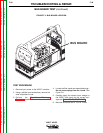
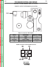
4. Locate the UPFR section on the main board
and associated plugs. Do not remove
plugs from the board. See Figure F.14.
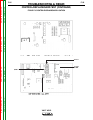
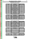
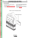
5. Carefully apply the correct input voltage to
the V205-T and check for the correct sec-
ondary voltages per tables F.10 & F11.
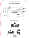
Voltage readings were taken with a Fluke
RMS meter. See Figure F.15 for joint loca-
tions.
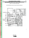
FIGURE F.14 UPFR LOCATION ON MAIN BOARD
BACK SIDE
MAIN BOARD
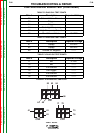
TABLE F.10 VOLTAGE CHECKS WITH 115 VAC APPLIED TO MACHINE
Generator/Mode
ON/STICK
ON/STICK
ON/STICK
ON/STICK
ON/STICK
ON/STICK
ON/STICK
Component
DD1
MF8
MF8
MF9
MF9
-------
TP20-TP9
Ref. Joint
A[-],K[+]
S[-],D[+]
S[-],G[+]
S[-],D[+]
S[-],G[+]
L10 (LED)
-------
Value
250-260 VDC
125 VDC
2.2 VDC
120 VDC
2.2 VDC
ON
385 VDC +/-5V
Generator/Mode
OFF
OFF
Component
F1
R82
Ref. Joint
-------
-------
Value
<1 OHM
46 OHM
TABLE F.11 RESISTANCE CHECKS