


Return to Section TOC Return to Section TOC Return to Section TOC Return to Section TOC
Return to Master TOC Return to Master TOC Return to Master TOC Return to Master TOC
V205-T AC/DC
TROUBLESHOOTING & REPAIR
F-54 F-54
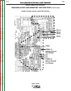
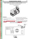
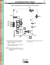
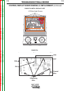
FIGURE F.27 – MAIN IGBT BOARD LOCATION
BACK SIDE
MAIN BOARD
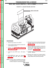
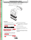
MAIN IGBT BOARD REMOVAL & REPLACEMENT (continued)
PROCEDURE
1. Remove input power to the V205-T.
2. Using a phillips head screwdriver remove the
case wraparound cover.
3. Perform the Input Filter Capacitor
Discharge Procedure detailed earlier in this
section.
4. Locate the main IGBT board. See Figure
F.27.
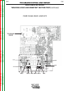
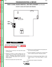
5. VERY CAREFULLY, label and disconnect
plugs CN1, CN2, CN3, CN4 & CN5. See
Figure F.28.
NOTE: All ribbon cable connections are secured
by a small amount of RTV on the outside
surface to keep the connections secure.
6. Using a 7mm nut driver, label and disconnect
leads RV1, RV2, RV3, RV4, RV5, RV6 & RV7.
See Figure F.28.
7. Using a phillips head screwdriver, remove the
thirty-two (32) phillips head screws from the
main board. Note washer positions for
replacement. See Figure F.28.
8. Carefully maneuver the main board out of the
machine. Replace.
9. Maneuver new board into its proper location
and secure to machine using the thirty-two
phillips head screws previously removed.