


PROCEDURE
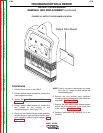
1. Remove the input power to the V205-T.
2. Using a phillips head screwdriver remove the
four screws from the corners of the name-
plate/keypad on the front of the machine. See
Figure F.30.
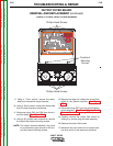
Observe static precautions detailed in PC Board
Troubleshooting Procedures at the beginning of
this section. Failure to do so can result in perma-
nent damage to equipment.
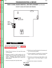
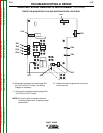
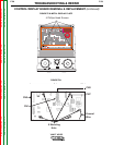
3. Tilt display plate forward and carefully label
and disconnect leads CN1, CN2, CN3 & CN7.
See Figure F.31.
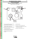
4. Disconnect the ground lead running from the
P.C. board to the machine frame. See Figure
F.31.
5. Carefully remove the board assembly.
NOTE: The board assembly is attached to the
nameplate/keypad and is to be replaced as
one unit.
6. Replace the board assembly.
7. Connect previously removed ground lead.
8. Connect previously removed leads CN1, CN2,
CN3, & CN7.
9. Replace the four phillips head screws previous-
ly removed from the corners of the name-
plate/keypad.
CAUTION
V205-T AC/DC
Return to Section TOC Return to Section TOC Return to Section TOC Return to Section TOC
Return to Master TOC Return to Master TOC Return to Master TOC Return to Master TOC
TROUBLESHOOTING & REPAIR
F-58 F-58
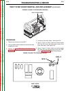
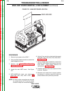
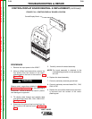
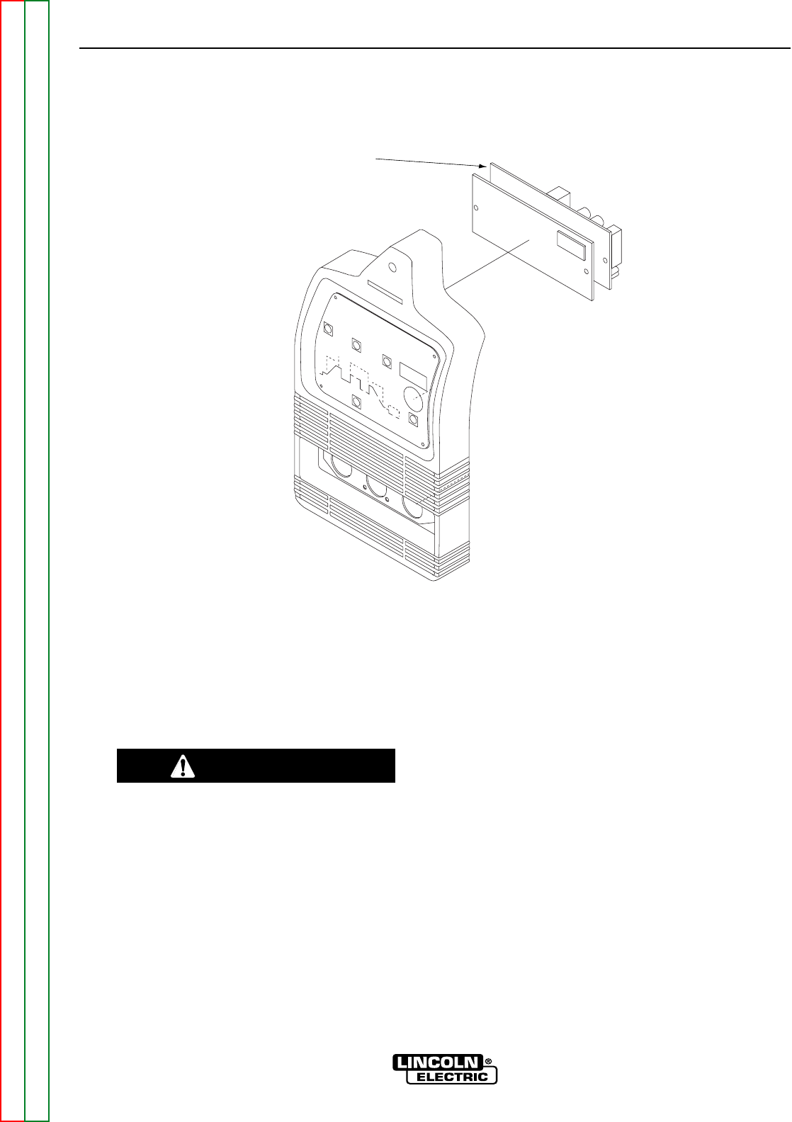
FIGURE F.29 – CONTROL/DISPLAY BOARD LOCATION
CONTROL/DISPLAY BOARD REMOVAL & REPLACEMENT (continued)
Control/Display Board