


21
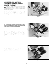
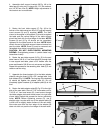
Fig. 48
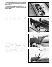
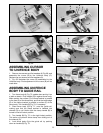
4. Assemble shelf support bracket (M) Fig. 48 to the
table legs (A) using two U-clamps (N), 1/4″ flat washers,
and 1/4-20 hex nuts (P). NOTE: Height adjustments to
the bracket can be made later.
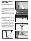
5. Fasten the front table support (F) Fig. 49 to the
bottom of the table using two #8 x 3/4″ long self tapping
wood screws (H) and (I) supplied. NOTE: The slots
closer to the angles in the support (F) should be against
the table and the vertical flange of the table support
should be flush with the front edge of the table. NOTE:
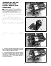
Screws (H) and (I) Fig. 49 should not be completely
tightened to the table board at this time. NOTE: Make
certain the end of the table support does not extend out
past the table. NOTE: Screw (I) must be removed and
reinstalled when table is mounted to the saw.
CAUTION: DO NOT OVER-TIGHTEN MOUNTING
SCREWS. Over-tightening screws in particle board may
cause them to strip.
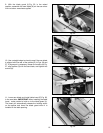
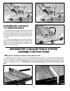
6. Fasten the rear table support (A) Fig. 50 to the saw
table. Insert a 3/8-16 x1″ hex head screw (B), through hole
in rear support and table, place a 3/8″ washer onto the
screw and thread a 3/8-16 hex nut onto screw and tighten.
Repeat this process for the remaining hole. Hole (C) is not
used on cast iron wing.
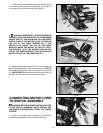
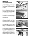
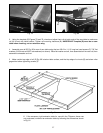
7. Assemble the three brackets (J) to the table adapter
plate (K) using the three 1/4-20 x 3/4″ carriage bolts, nuts
and washers (Fig. 51). NOTE: The long leg of the brackets
(J) should be against the adapter plate (K). Do not
completely tighten brackets (J) to adapter plate (K) at this
time.
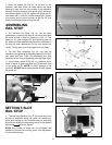
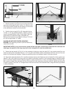
8. Fasten the table adapter plate (B) Fig. 52 to the right
side of the saw table. Place a 7/16″ lockwasher onto a
7/16-20 x1″ hex head screw (D), insert screw through
the table adapter plate and thread screw into right side
of saw table. Repeat this process for the two remaining
holes. NOTE: Before tightening screws (D), use a
straight edge to make sure top of the adapter plate (B)
is level with or slightly below surface of the saw table.
Also make sure that the front edge of the adapter (B)
does not stick out past the front edge of the saw table.
N
M
P
N
Fig. 49
Fig. 50
A
B
B
F
H
I
C
D
Fig. 51
J
K
Fig. 52
B
D