


23
Fig. 59
Fig. 60
Fig. 61
Fig. 62
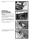
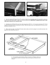
ASSEMBLING
UNIFENCE GUIDE RAIL
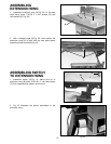
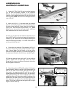
1. Locate the T-Slot Guide Rail and mounting hardware
Fig. 59 from the packing material of the Unifence.
Remove the end caps (A) Fig. 59, prior to assembly, by
inserting a flat headed screwdriver (B) into the channel
and tap gently. NOTE: Take care not to damage either the
cap or the rail.
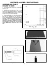
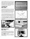
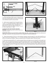
2. Insert two 3/8-24 x 1″ hex head bolts, flat washers
and hex nuts (C) Fig. 60 into the two holes (F) Fig. 60 in
the front of saw table (G). Screw bolts into nuts slightly
leaving bolt head extended approximately 1/2″. Note:
Make sure to use only the two holes shown at (F) and
that washers are on the nut side of the bolt.
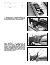
3. Insert one 1/4-20 x 3/4″ hex head bolt, flat washer and
hex nut (D) Fig. 60, into the front support of the extension
table (E) Fig. 60. Screw bolt into nut slightly leaving bolt
head extended approximately 1/4″. Make sure washer is
on the nut side of the bolt.
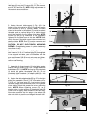
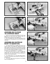
4. From either end, slide the T-Slot guide rail (A) Fig. 61
on the hex head of the bolts partially inserted in step 2
and 3 above. Note: The bolt heads on the saw table,
slide into the upper t-slot (B) Fig. 61 and the bolt head on
the extension table slide into the lower t-slot (C) Fig. 61.
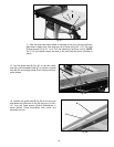
5. Slide the guide rail along until the 0” on the unifence
scale is aligned with the right edge of the saw table.
Snug the hex nuts on the saw and extension table, but
do not tighten at this time.
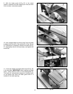
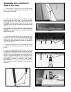
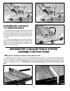
6. Adjust the guide rail (C) Fig. 62 parallel with the saw
table surface by placing a square (H) on the saw table at
both the left front end of the saw table (A) and the right
front end of the extension table (B), with the rule of the
square against the flat surface on top of the guide rail.
The guide rail (C) Fig. 62, can be adjusted up or down
slightly at either end. After being certain the guide rail is
parallel with the table surface, firmly tighten the two hex
nuts that fasten the guide rail to the table. Note: Make
sure 0” (D) on the unifence scale is aligned with the right
edge of the saw table (E).
C
F
G
D
E
A
C
B
C
H
D
E
0"
A
B
A
A
B