


26
Fig. 75
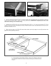
Fig. 76
Fig. 74
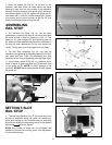
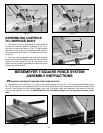
ASSEMBLING UNIFENCE
TO UNIFENCE BODY
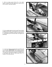
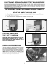
1. The fence (A) can be assembled to clamp plate (B)
in either the horizontal position as shown in Fig. 74, or
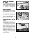
the vertical position as shown in Fig. 75. Make certain
that the two lock knobs (C) are loose and slide fence (A)
onto clamp plate (B) as shown. Then tighten the two lock
knobs (C).
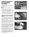
2. For most cutting operations, the bottom of the fence
should be positioned slightly above the table surface.
Loosen two lock knobs (C) Fig. 76, and place a thin
object such as a scale (D) between the table and fence.
Tighten two lock knobs (C).
C
B
A
C
A
B
C
D
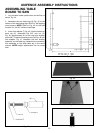
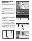
BIESEMEYER T-SQUARE FENCE SYSTEM
ASSEMBLY INSTRUCTIONS
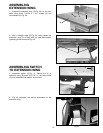
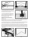
1. WARNING: DISCONNECT MACHINE FROM POWER SOURCE.
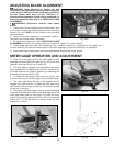
2. Assemble the front rail (A) Fig. 77 to front of saw table using the two 3/8-16 x 1-1/4″ long flat head Phillips screws
(B), 7/8″ flat washers, lock washers and 3/8-16 hex nuts supplied. Screws (B) are inserted through the two holes in the
front rail, and through the two through-holes in the front of the saw table, and fastened to the table with the flat
washers, lockwashers, and hex nuts. IMPORTANT: Do not completely tighten front rail mounting hardware at this
time.
Fig. 77
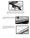
Fig. 78
B
A
D
B