


45
BIESEMEYER T-SQUARE FENCE SYSTEM
FENCE OPERATION
IMPORTANT: Before operating fence, make sure the fence is adjusted parallel to
the miter gage slot, as explained later in this manual.
Fig. 142
Fig. 143
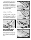
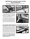
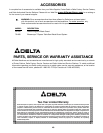
1. To move the fence along the guide rail, simply lift up
clamp lever (A) as shown in Fig. 142, slide fence to
desired position on rail, and push down on clamp lever
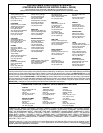
(A) as shown in Fig. 143. NOTE: A magnet (E) Fig. 143,
is provided to hold clamp handle (A) Figs. 142 and 143,
in the up position when moving the fence.
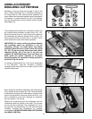
2. The distance the fence is positioned away from the
blade is indicated by the witness line (B) Fig. 144,
located on the cursor (C). To adjust the cursor (C), make
a test cut with the fence locked in position. Measure the
width of the finished cut and adjust the cursor (C) by
loosening the two screws (D), adjusting the cursor (C)
until the witness line (B) is aligned with the same marking
on the scale as the finished cut. Tighten the two screws
(D).
Fig. 144
A
E
A
C
B
D
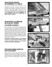
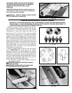
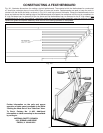
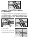
ADJUSTING FENCE PARALLEL TO MITER GAGE SLOTS
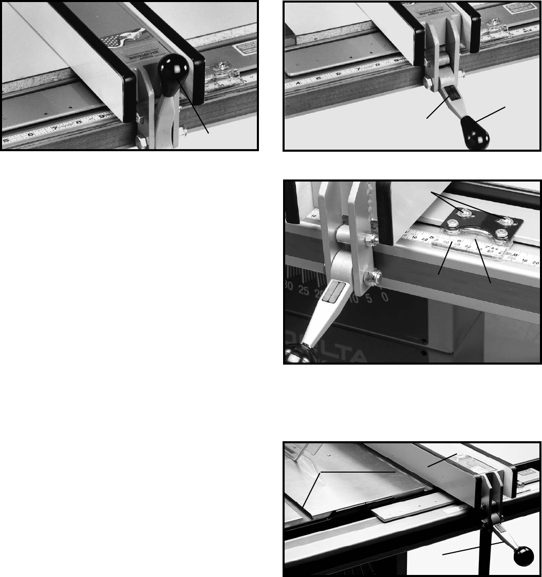
Adjust the fence (A) Fig. 145 so that it is parallel to the
miter gage slots (B). To check and adjust, move fence (A)
until the bottom edge of the fence is in line with the edge
of one of the miter gage slots, and push down on the
fence clamping lever (C). Check to see if the fence (A) is
parallel to the miter gage slot the entire length of the
table. If an adjustment must be made, lift up fence
locking lever (C) and raise fence up off the guide tube,
(Fig. 146). Tighten or loosen one of the two adjusting
screws (D) or (E) Fig. 146, using a 3/16″ allen wrench (F),
not supplied. Replace the fence on the guide tube and
check again to see if the edge of the fence is parallel
with the miter gage slot along the entire length of the
slot. Repeat this adjustment until the fence is parallel
with the miter gage slot. IMPORTANT: VERY LITTLE
MOVEMENT OF SCREWS (D) AND (E) IS
NECESSARY TO ADJUST THE FENCE PARALLEL
WITH THE MITER GAGE SLOT.
Fig. 145
B
A
C