


28
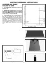
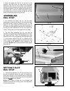
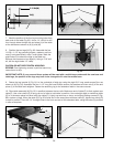
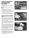
7. Mark the position of the four leg mounting holes from
each end of the table (Fig. 82). Use a 1/4″ drill bit to drill
four through holes through the end piece (J) of the table
at the dimensions shown at (K) (L) and (M).
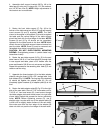
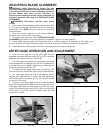
8. Position the two legs (H) Fig. 83. Assemble the four
1/4-20 x 1-1/2″ leg mounting screws, washers, and hex
nuts (I) into holes drilled in step 7 and tighten. Mark the
eight holes (P) to attach the legs to the table top.
Remove the screws and two legs (H). Using a 1/16″ drill
bit, drill the eight holes 1/2″ deep.
CAUTION: DO NOT OVER-TIGHTEN MOUNTING
SCREWS. Over-tightening screws in particle board may
cause them to strip.
IMPORTANT NOTE: If your saw and fence system will be used with a mobile base underneath the saw base and
table legs, the position of the legs may have to be changed to fit onto the mobile base.
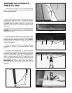
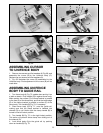
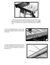
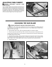
9. Fasten the leg bracket (L) Fig. 84, to the underside of table top using the eight 3/4″ long wood screws [four are
shown at (N) Fig. 84]. Assemble the four 1-1/2″ long flat head Phillips screws, flat washers and hex nuts (I) to the end
piece (J) of the table and retighten. Fasten the remaining leg to the extension table in the same manner.
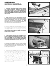
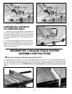
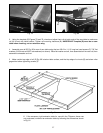
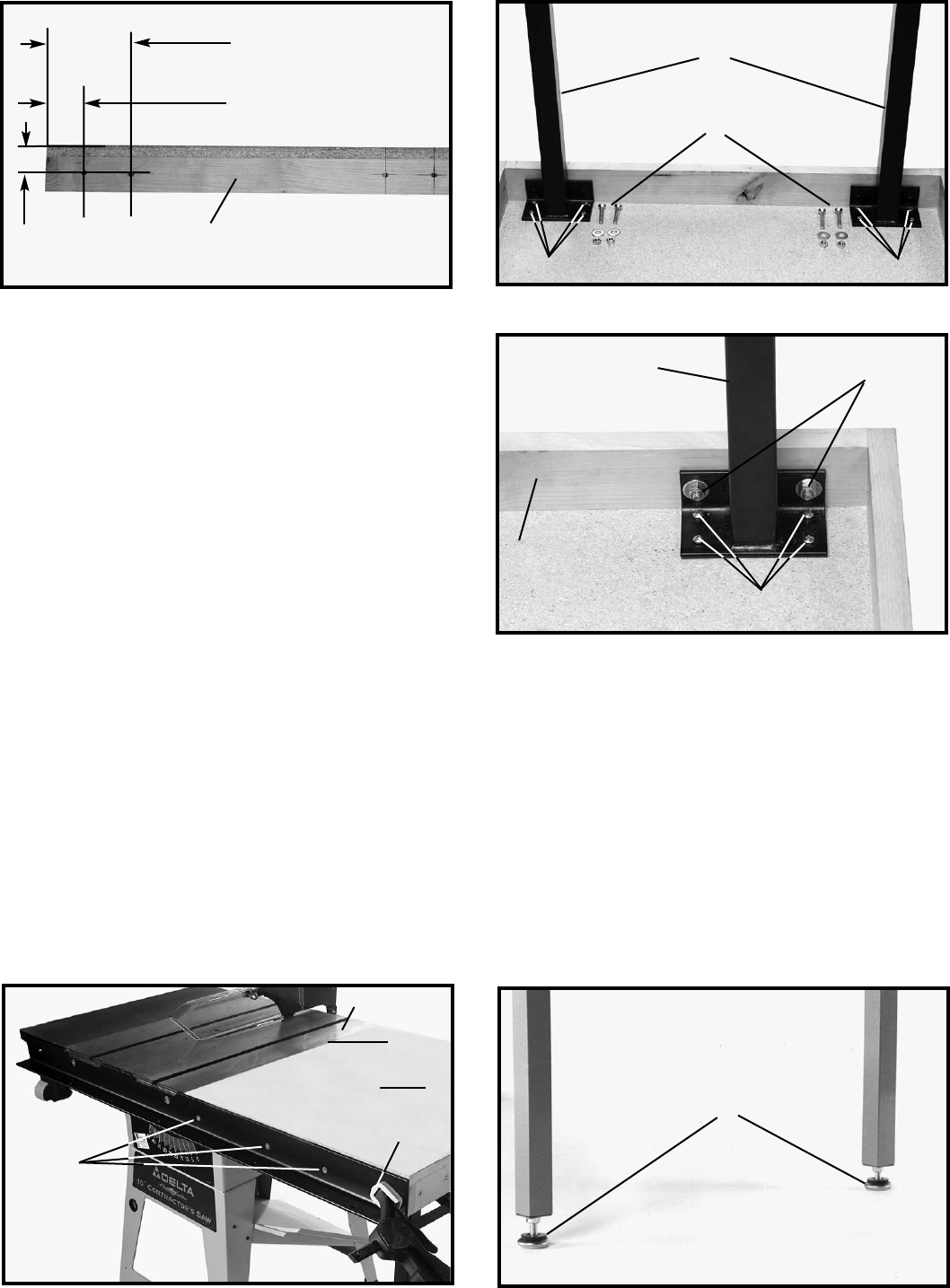
10. Place table assembly (N) Fig. 85, in position between the two rails. Make sure end of table (O) is flush against saw
table (P). Use a bar clamp (Q) to snug up end of rails to hold table in position. Use a straight edge to make sure table
(O) is in the same plane and level with saw table (P). Lightly tap table up or down, and adjust leveling screws (R) Fig.
86 in bottom of legs. When the table (O) Fig. 85 is level and in the same plane with saw table (P), tighten bar clamp (Q)
to hold in position. Then drill 1/4″ through-holes in the front and rear of the extension table, using the holes (S) provided
in rails as template.
Fig. 83
Fig. 82
1- 3/4
″″
(K)
3
″″
(L)
5- 3/8
″″
(M)
J
H
I
PP
Fig. 84
L
J
N
I
Fig. 85
Fig. 86
N
O
P
Q
S
R