


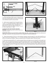

ADJUSTING BLADE ALIGNMENT
WARNING: Blade Alignment is Factory Set and
should not need adjustment. Adjusting Blade Alignment,
in the field is a difficult and time-consuming procedure.
All Saw Blades have some run-out. Therefore, re-
adjusting blade alignment should only be attempted if it
becomes necessary. (See step 6 in CHECKING BLADE
ALIGNMENT.)
1. WARNING: Disconnect machine from power
source.
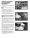
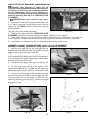
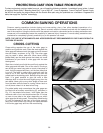
2. Lower blade. Remove blade guard and table insert. With
a 1/2″ wrench, loosen the 4 front and rear trunnion mounting
bolts (E) Fig. 101C. NOTE: Only the 2 rear trunnion mounting
bolts are shown.
3. Move the trunnion assembly in the desired direction.
Tap gently with rubber mallet if necessary.
4. To check blade alignment, follow (CHECKING BLADE
ALIGNMENT) procedure until proper alignment is achieved. Tighten 4 trunnion bolts (E).
5. Check blade alignment again after tightening bolts to confirm alignment. If alignment is off, loosen the 4
trunnion bolts (E) and repeat the above steps until proper alignment is achieved with bolts fully tightened.
6. Install table insert, blade guard, and lower blade before reconnecting power source.
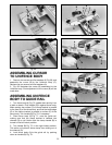
MITER GAGE OPERATION AND ADJUSTMENT
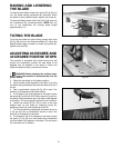
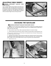
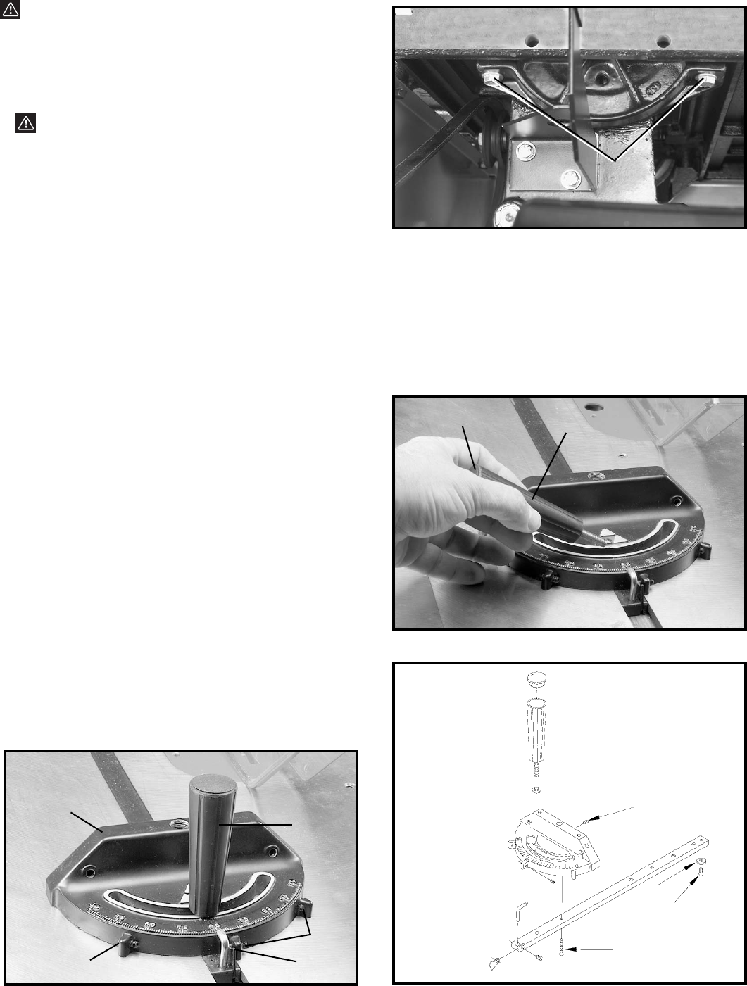
1. Insert the miter gage bar into the miter gage slot and
assemble the washer and lock handle (A) Fig. 102, to the miter
gage bar. Insert cap (K) into top of handle (A).
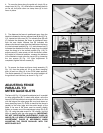
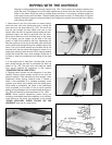
2. The miter gage is equipped with adjustable index stops
at 90 degrees and 45 degrees right and left. Adjustment to
the index stops can be made by tightening or loosening the
three adjusting screws (B) Fig. 103.
3. To rotate the miter gage, loosen lock knob (A) Fig. 103,
and move the body of the miter gage (C) to the desired angle.
4. The miter gage body will stop at 90 degrees and 45
degrees both right and left. To rotate the miter gage body
past these points, the stop link (D) Fig. 103, must be moved
up and out of the way.
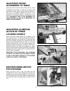
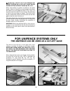
5. The head of the miter gage pivots on a special tapered
screw (G) that fastens the head to the miter gage bar. If the
miter gage head does not pivot freely, or pivots too freely,
adjust it by loosening set screw (H) Fig. 104, and turning the
screw (G), in or out. Be certain to tighten screw (H) after
adjustment is made.
33
Fig. 103
A
B
D
B
C
Fig. 101C
Fig. 102
Fig. 104
H
G
E
F
E
A
K