


24
Fig. 64
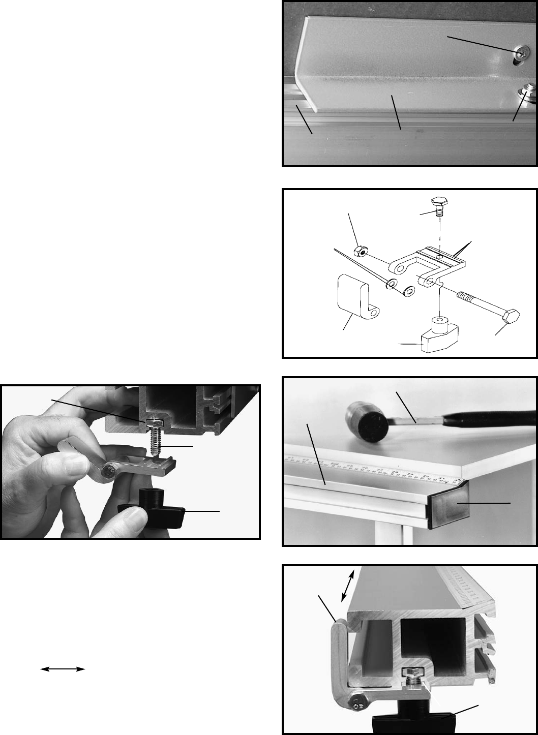
Fig. 65
Fig. 67
Fig. 63
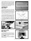
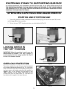
7. Move the square (H) Fig. 62, to the end of the
Unifence table and check to make certain the same
distance is kept from the top surface of the extension
table (K) to the top surface of the guide rail (C). Move the
front table support (L) Fig. 63, against the guide rail (C),
and fasten with 1/4-20 nut and flat washer (M). Tighten
two screws, one of which is shown at (N) Fig. 63, that
fasten the Unifence table to the guide rail.
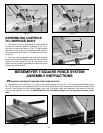
SETTING T-SLOT
RAIL STOP
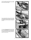
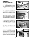
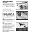
1. The Rail Stop Assembly Fig. 67 (A) can be set to any
number of positions along the guide rail providing a
quick stop setting for the Unifence body by loosening
knob (B) and sliding the stop along the rail to the desired
position ( ) and re-tighten.
NOTE: Any number of stops can be purchased and
installed to provide time saving quick stop adjustment
for the Unifence body.
Fig. 66
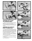
ASSEMBLING
RAIL STOP
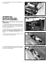
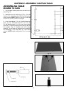
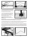
1. The Unifence Flip Stop, Fig. 64, can be easily
assembled by inserting flip stop (A) into fence slide stop
(B) which is held in place by inserting 1/4-20 x 2″ hex
head bolt (C), fiber washers (D) and tightening hex nut
(E). Make sure fiber washers are placed on both sides of
flip stop (A) when assembled. Do not over tighten hex
nut (E). The flip stop must fit snuggly but move freely.
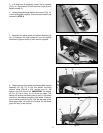
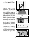
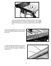
2. The Rail Stop Assembly, Fig. 65, can then be
attached to the guide rail by inserting head of 5/16-18 (F)
hex head bolt into T-Slot (G) positioning the stop
assembly to the rail and tightening knob (H) finger tight.
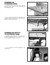
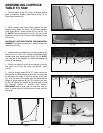
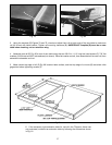
3. Use a rubber mallet (P) Fig. 66, or a hammer and a
block of wood, to gently tap end cap (R) into both ends
of the guide rail (C). NOTE: To avoid damage to the
guide rail, DO NOT use a metal hammer directly against
the guide rail.
R
P
C
M
N
L
C
A
B
C
D
E
F
G
H
A
B
F
H