


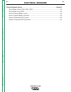
ELECTRICAL DIAGRAMS
G-7 G-7
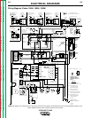
IDEALARC CV-400
Return to Section TOC Return to Section TOC Return to Section TOC Return to Section TOC
Return to Master TOC Return to Master TOC Return to Master TOC Return to Master TOC
1 AMP/400 VOLT (UNLESS OTHERWISE SPECIFIED)
LM124 (UNLESS OTHERWISE SPECIFIED)
COMMON CONNECTION
=
=
OP AMPS
=
DIODES
=
RESISTORS
MFD/VOLTS
ON 3 PLACE DECIMALS IS + .OO2
=
CAPACITORS
ELECTRICAL SYMBOLS PER E1537
J5
6
OHMS,1/4 WATT (UNLESS OTHERWISE SPECIFIED)
S
NONE
SHT.
ON HOLES SIZES PER E-2056
19687
EQUIP.
NO.
THE LINCOLN ELECTRIC CO.
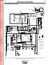
IDEALARC DC400
Ch’ge.Sht.No.
ON 2 PLACE DECIMALS IS + .O2
SUBJECT
MATERIAL TOLERANCE ("t") TO AGREE
CLEVELAND, OHIO U.S.A.
ON ALL ANGLES IS + .5 OF A DEGREE
CHK.
UNLESS OTHERWISE SPECIFIED TOLERANCE
19687
DR.
DATE
TYPE
S
SUP’S’D’G.
SCALE
MCW
WITH PUBLISHED STANDARDS
FILENAME: S19687_3EA
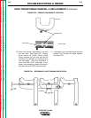
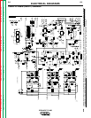
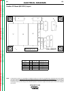
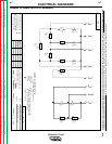
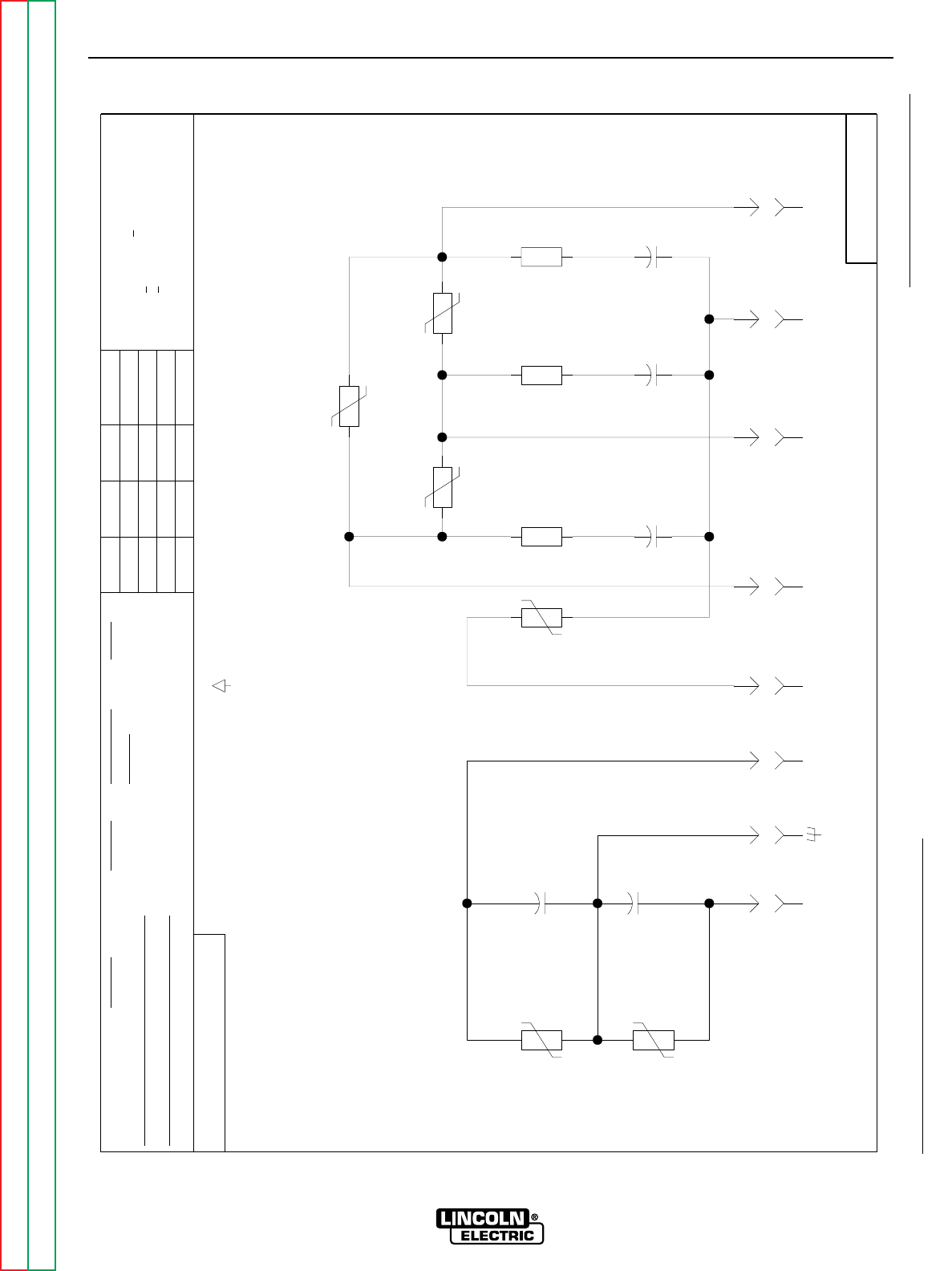
SNUBBER SCHEMATIC
3-26-90
38J
130V
TP3
J5
8
J5
3
J5
2
J5
4
5W
10
R2
5W
10
R3
400V
.68
C2
38J
130V
TP2
38J
130V
TP1
400V
.68
C1
5W
10
R1
400V
.68
C3
221
222
223
204
J5
5
J5
1
80J
150V
TP6
160J
320V
TP5
160J
320V
TP4
600V
.05
C4
600V
.05
C5
J5
7
224220 225
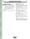
GENERAL INFORMATION
3-8-91G
12-20-96F
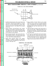
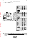
Snubber PC Board (M15370-3) Schematic
NOTE: Lincoln Electric assumes no responsibility for liablilities resulting from board level troubleshooting. PC Board repairs will invalidate your factory warranty. Individual Printed Circuit Board
Components are not available from Lincoln Electric. This information is provided for reference only. Lincoln Electric discourages board level troubleshooting and repair since it may com-
promise the quality of the design and may result in danger to the Machine Operator or Technician. Improper PC board repairs could result in damage to the machine.