


Return to Section TOC Return to Section TOC Return to Section TOC Return to Section TOC
Return to Master TOC Return to Master TOC Return to Master TOC Return to Master TOC
TROUBLESHOOTING & REPAIR
F-11 F-11
IDEALARC CV-400
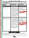
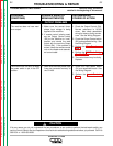
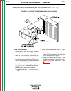
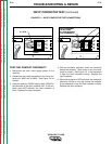
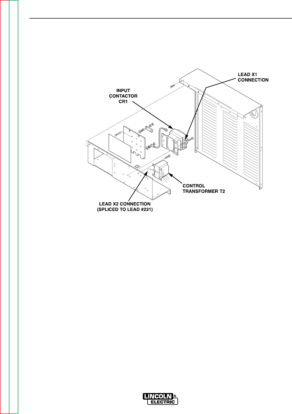
FIGURE F.1 – CONTROL TRANSFORMER AND LEAD LOCATIONS
CONTROL TRANSFORMER (T2) VOLTAGE TEST (continued)
TEST PROCEDURE
1. Disconnect the main input supply power to
the machine.
2. With the 5/16” nut driver, remove the top,
case sides, and rear input panel.
3. Locate the control transformer (T2) on the
left side of the input box (facing the back of
the machine). See Figure F.1.
4. Locate the control transformer primary leads
(H1, H2, H3, etc.). See the Wiring Diagram.
NOTE: Unused leads should be taped.
a. Inspect for broken or incorrect connec-
tions.
5. Locate control transformer leads X1 (top)
and X2.
a. Lead X1 is connected to the input con-
tactor (CR1) coil located on the input side
of the contactor. See Figure F.1.
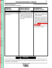
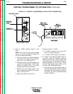
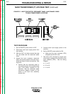
b. Lead X2 is spliced into lead #231. See
the Wiring Diagram. Lead #231 is con-
nected to the power switch (S1). See
Figure F.2.