


Return to Section TOC Return to Section TOC Return to Section TOC Return to Section TOC
Return to Master TOC Return to Master TOC Return to Master TOC Return to Master TOC
TROUBLESHOOTING & REPAIR
F-18 F-18
IDEALARC CV-400
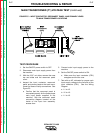
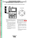
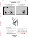
8. Read the meter.
a. If proper voltage is present for all three
phases, proper main input supply volt-
age is being supplied.
b. If proper voltage is not present in any
or all of the three phases, check input
fuses and leads.
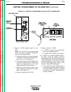
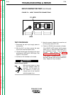
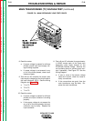
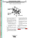
9. Test with an AC voltmeter for proper main
input supply voltage from the output side of
the input contactor (CR1). See the Wiring
Diagram and Figure F.5.
a. T1 to T2.
b. T2 to T3.
c. T1 to T3.
10. Read the meter.
a. If proper voltage is present for all three
phases, the input contactor is working
properly.
b. If the proper voltage is not present for
any or all of the three phases, the input
contactor may be faulty. Replace the
input contactor.
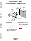
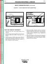
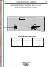
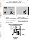
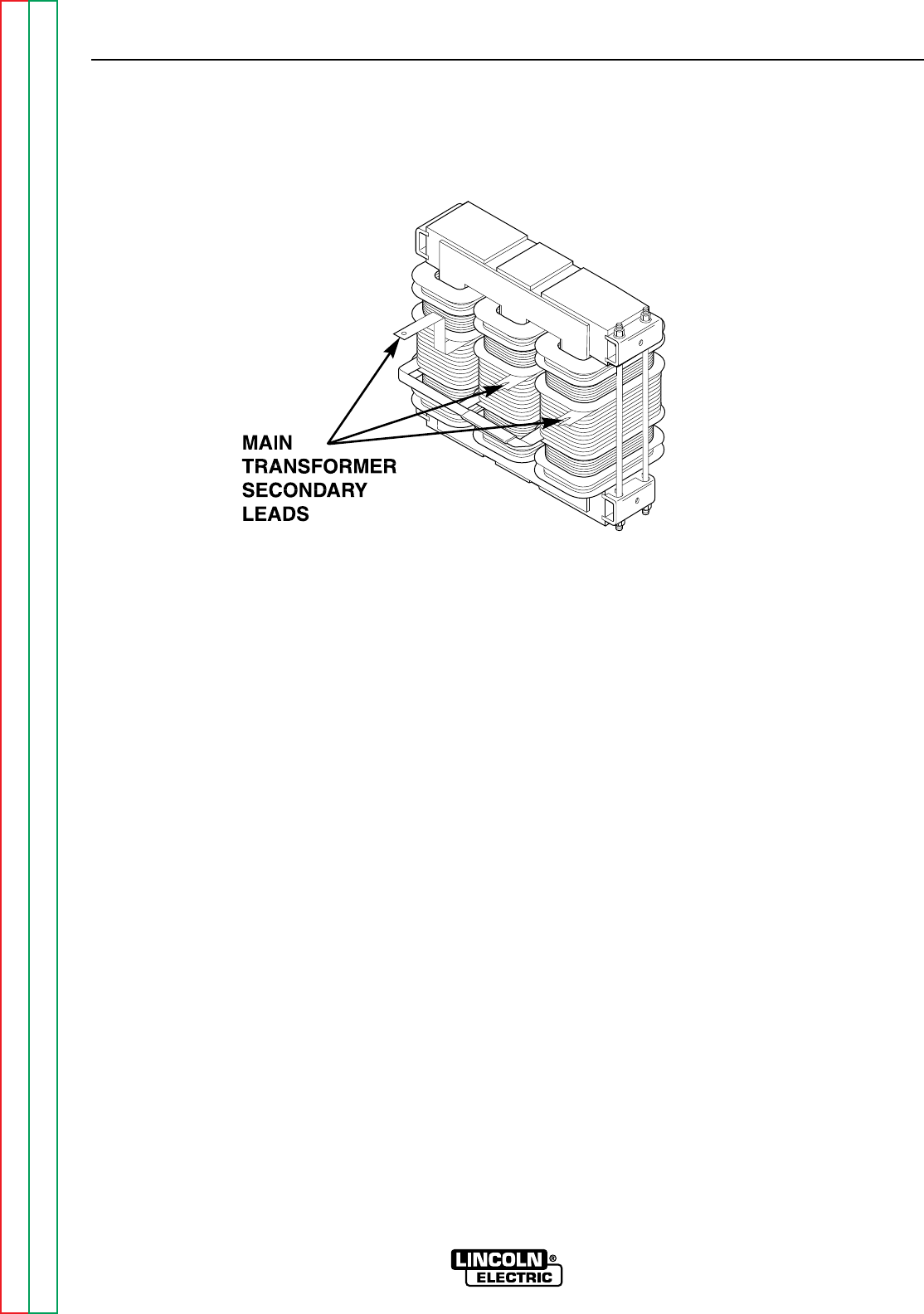
11. Test with an AC voltmeter for approximate-
ly 42VAC across each of the three main
secondary start leads located at the
SCR/Diode Rectifier Bridge. Remove the
red insulating paint to achieve good con-
tact if necessary. See Figure F.6. See the
Wiring Diagram.
a. If one or more of the above voltage
tests are incorrect, check for loose or
faulty connections.
b. If the connections are good, then the
main transformer may be faulty. Re-
place the main transformer.
MAIN TRANSFORMER (T1) VOLTAGE TEST (continued)
FIGURE F.6 – MAIN SECONDARY LEAD TEST POINTS