


Return to Section TOC Return to Section TOC Return to Section TOC Return to Section TOC
Return to Master TOC Return to Master TOC Return to Master TOC Return to Master TOC
TROUBLESHOOTING & REPAIR
F-23 F-23
IDEALARC CV-400
STATIC SCR/DIODE RECTIFIER BRIDGE TEST (continued)
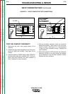
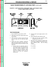
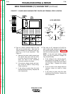
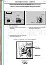
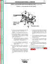
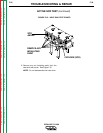
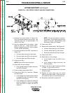
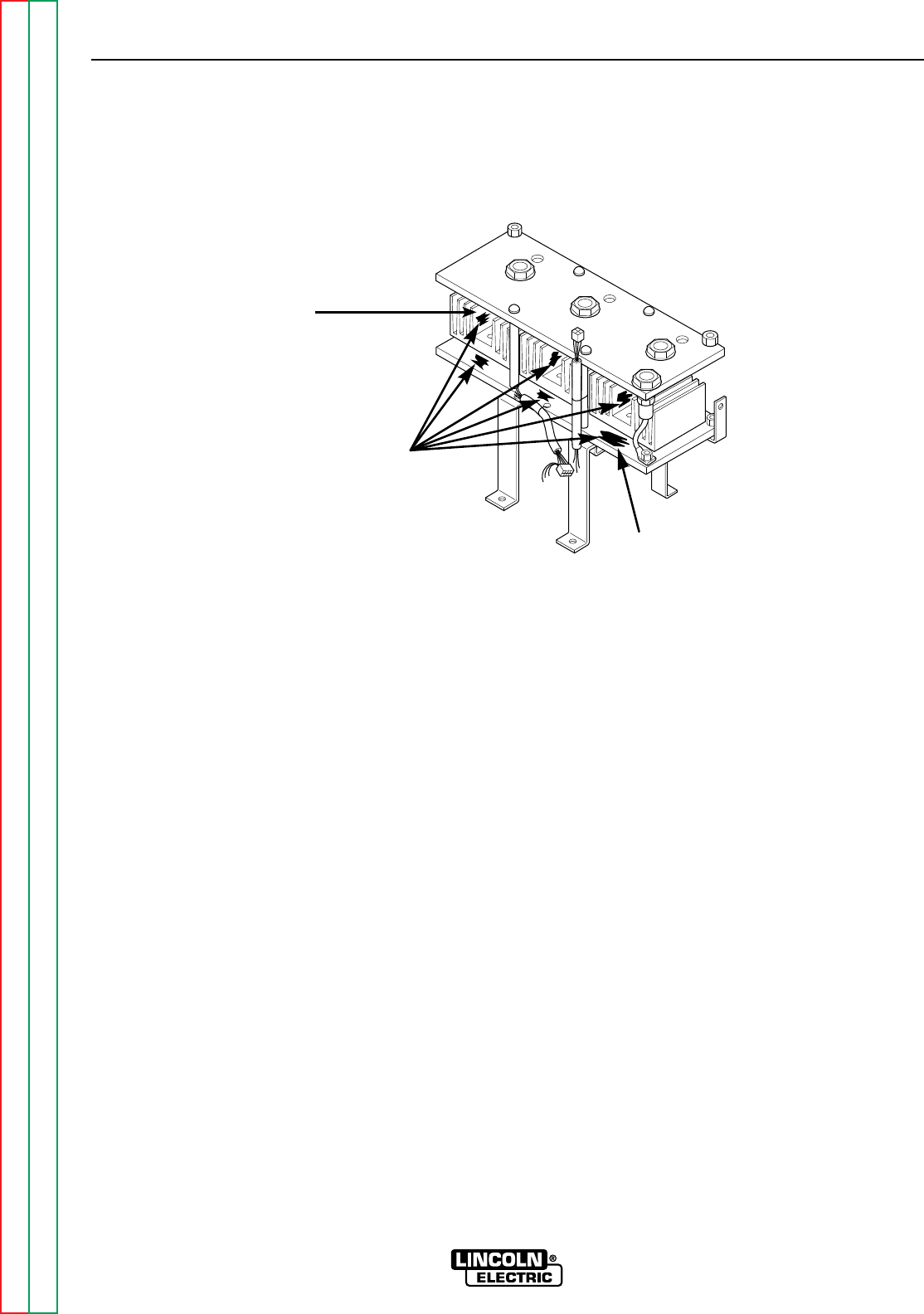
8. Remove any red insulating paint from the
heat sink test points. See Figure F.11.
NOTE: Do not disassemble the heat sink.
9. Measure the resistance from the anode to
the cathode of SCR 1 using an analog
volt/ohmmeter (multimeter) set at R x 1000
scale. See Figure F.11.
a. Reverse the meter leads and measure
the resistance from the cathode to the
anode of SCR 1. See Figure F.11.
b. If a low resistance is measured in
either meter polarity, SCR 1 is faulty.
Replace SCR 1.
10. Test the resistance of SCR 2 and SCR 3
using the same procedure described in
Step 9.
11. Measure the resistance of diode D1 from
anode (+probe) to cathode (-probe) using
an analog ohmmeter set at R x 1000 scale.
The resistance should be low. See Figure
F.11.
a. Reverse the meter leads and measure
the resistance from cathode (+probe)
to anode (-probe) of diode D1. The
resistance should be high. See Figure
F.11.
b. If a low resistance is measured in both
meter polarities, diode D1 is shorted.
Replace diode D1.
c. If a high resistance is measured in both
meter polarities, diode D1 is open.
Replace diode D1.
12. Test diodes D2, D3 and D4 for proper oper-
ation using the same procedure described
in Step 11.
13. Reconnect all leads and molex plugs.
14. If this test did not identify the problem or to
further test the SCRs, go to the Active
SCR Test.
FIGURE F.11 – HEAT SINK AND SCR TEST POINTS
REMOVE ANY
INSULATING
PAINT
CATHODE (SCR)
SCR
ANODE