


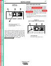
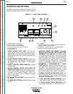

1. POWER SOURCE PILOT LIGHT: This light indi-
cates that the power source input contactor is ener-
gized (closed). This also means that the main power
transformer and all auxiliary control transformers are
energized.
2. ON/OFF POWER TOGGLE SWITCH: Energizes or
deengergizes the input contactor. The switch turns
the machine ON or OFF. Position "I" is ON; position
"0" is OFF.
3. OUTPUT CONTROL POTENTIOMETER: Controls
output voltage.
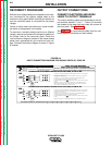
4. OUTPUT CONTROL SWITCH (WITH LOCAL OR
REMOTE POSITIONS): Selects the mode of control.
In the "Local" position, control is by the machine con-
trol panel. In the "Remote" position, control is by
either a wire feeder unit or through an optional
remote control device.
5. DC VOLTMETER (OPTIONAL): Displays actual out-
put voltage.
6. DC AMMETER (OPTIONAL): Displays actual output
current.
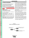
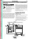
7. AUXILIARY POWER AND REMOTE CONTROL
CONNECTIONS FOR WIRE FEEDER AND OTHER
EQUIPMENT (115V AND 42V): The 14-pin amphe-
nol receptacle provides either 115 or 42 VAC as well
as remote control connections. Terminal strips with
screw connections are located behind the hinged
control panel for hard wired control. A strain relief
connector is provided for cable entry. The 42 VAC
auxiliary is not available at the terminal strip.
8. VOLTMETER "+" ELECTRODE OR "-" ELEC-
TRODE SWITCH: Selects the electrode polarity for
the remote work sensing lead (#21) when using
automatic or semiautomatic wire feeders. It must
agree with the actual electrode polarity chosen and
with the wire feeder polarity switch on the feeder.
9. THERMAL PROTECTON INDICATOR LIGHT: This
light indicates that either of the two protective ther-
mostats has opened. Welding output is disabled but
input power is still applied.
10. 42 VAC AUXILIARY CIRCUIT BREAKER: This 10
amp breaker protects the 42 VAC auxiliary circuit.
11. 115 VAC AUXILIARY CIRCUIT BREAKER: T
his 10
amp breaker protects the 115 VAC auxiliary circuit.
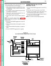
CONTROLS AND SETTINGS
All operator controls and settings are located on the
case front assembly. See Figure B.1 for their locations.
OPERATION
B-5 B-5
IDEALARC CV-400
Return to Section TOC Return to Section TOC Return to Section TOC Return to Section TOC
Return to Master TOC Return to Master TOC Return to Master TOC Return to Master TOC
FIGURE B.1 – CASE FRONT CONTROLS
8
9
1
2
34567
10
11
1. POWER SOURCE PILOT LIGHT
2. ON/OFF POWER TOGGLE SWITCH
3. OUTPUT CONTROL POTENTIOMETER
4. OUTPUT CONTROL SWITCH (WITH LOCAL OR
REMOTE POSITIONS)
5. DC VOLTMETER
6. DC AMMETER
7. AUXILIARY POWER CONNECTIONS FOR WIRE FEEDER AND
OTHER EQUIPMENT (115V AND 42V)
8. VOLTMETER "+" ELECTRODE OR "-" ELECTRODE SWITCH
9. THERMAL PROTECTION INDICATOR LIGHT