


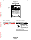
RECONNECT PROCEDURE
Multiple input voltage welders are shipped from the fac-
tory connected for the highest voltage listed on the
machine's rating plate. Before installing the welder, be
sure the reconnect panel is connected for the proper
voltage.
Failure to follow these instructions can cause immedi-
ate failure of components in the welder.
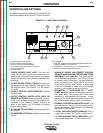
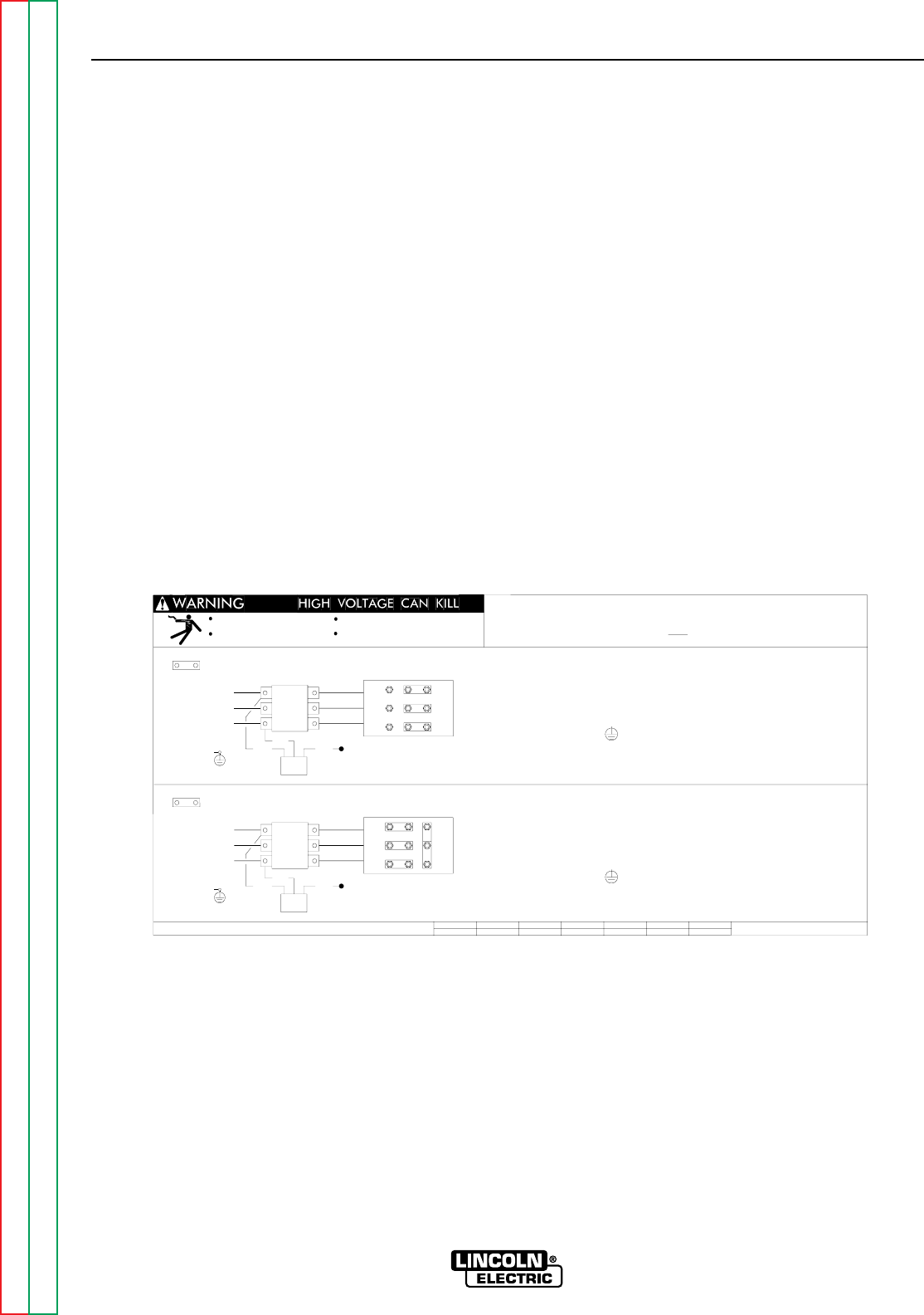
To reconnect a multiple voltage machine to a different
voltage, remove input power and change the position of
the jumper links on the reconnect panel. Follow the
input connection diagram, located on the inside access
panel cover, appropriate for your machine's input volt-
age. This same connection diagram is shown in Figure
A.4 below.
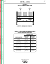
OUTPUT CONNECTIONS
CONNECT ELECTRODE AND WORK
LEADS TO OUTPUT TERMINALS
The output (welding) cables are connected to the out-
put terminals marked "+" and "-" . These 1/2" terminals
are located at the lower right and lower left corners of
the front panel. See
Figure A.5
.
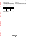
See
Table A.1
for recommended cable sizes for com-
bined lengths of electrode and work cables.
INSTALLATION
A-6 A-6
IDEALARC CV-400
Return to Section TOC Return to Section TOC Return to Section TOC Return to Section TOC
Return to Master TOC Return to Master TOC Return to Master TOC Return to Master TOC
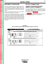
FIGURE A.4
INPUT CONNECTION DIAGRAM FOR 230/460 VOLTS AC, 50/60 HZ
THE LINCOLN ELECTRIC CO., CLEVELAND OHIO U.S.A.
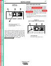
1. TURN OFF THE INPUT POWER USING THE DISCONNECT SWITCH AT THE FUSE BOX.
CONNECTION FOR LOWEST RATING PLATE VOLTAGE, 50 OR 60 HZ.
CONNECTION FOR HIGHEST RATING PLATE VOLTAGE, 50 OR 60 HZ.
CODES.
4. CONNECT TERMINAL MARKED TO GROUND PER LOCAL AND NATIONAL ELECTRIC
LEAST 600 VOLT INSULATION.
2. DISCONNECT AND INSULATE THE H2 LEAD TERMINAL WITH TAPE TO PROVIDE AT
5. MOUNT THE LINKS IN THE POSITIONS SHOWN WITH THE PROVIDED HEX NUTS.
USE. SECURE THE REMAINING HEX NUTS IN PLACE.
DOUBLE UP THE LINKS IN TWO OF THE POSITIONS TO SAVE THEM FOR FUTURE
5. MOUNT THE LINKS IN THE POSITIONS SHOWN WITH THE PROVIDED HEX NUTS.
LINK
1. TURN OFF THE INPUT POWER USING THE DISCONNECT SWITCH AT THE FUSE BOX.
CODES.
4. CONNECT TERMINAL MARKED TO GROUND PER LOCAL AND NATIONAL ELECTRIC
LEAST 600 VOLT INSULATION.
2. DISCONNECT AND INSULATE THE H3 LEAD TERMINAL WITH TAPE TO PROVIDE AT
3. CONNECT L1, L2 & L3 INPUT SUPPLY LINES AND H2 TRANSFORMER LEADS
TO THE INPUT SIDE OF THE CR1 CONTACTOR AS SHOWN.
3. CONNECT L1, L2 & L3 INPUT SUPPLY LINES AND H3 TRANSFORMER LEADS
TO THE INPUT SIDE OF THE CR1 CONTACTOR AS SHOWN.
INPUT SUPPLY CONNECTION DIAGRAM
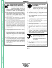
Do not touch electrically live parts
Only qualified persons should install,
use or service this equipment
removed
servicing
Do not operate with covers
Disconnect input power before
NOTE: MACHINES ARE SHIPPED FROM FACTORY CONNECTED FOR OVER 300 VOLTS
DUAL VOLTAGE MACHINE
GND
H2
INPUT
LINES
L1
H1
L2
L3
{
CR1
V
U
W
CONTACTOR
H3
PILOT
TRANSF.
LINK
GND
H3
INPUT
LINES
L1
H1
L2
L3
{
CR1
V
U
W
CONTACTOR
H2
PILOT
TRANSF.
IMPORTANT: CHANGE LINK POSITIONS AND PILOT TRANSFORMER CONNECTIONS.