


Return to Section TOC Return to Section TOC Return to Section TOC Return to Section TOC
Return to Master TOC Return to Master TOC Return to Master TOC Return to Master TOC
TROUBLESHOOTING & REPAIR
F-53 F-53
IDEALARC CV-400
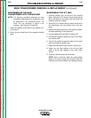
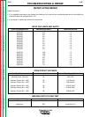
RETEST AFTER REPAIR
Retest a machine:
• If it is rejected under test for any reason that requires you to remove any mechanical part which could affect the
machine’s electrical characteristics. OR
• If you repair or replace any electrical components.
INPUT IDLE AMPS AND WATTS
Input Volts/Phase/Hertz Maximum Idle Amps Maximum Idle KW
200/3/60 10.9 1.2
208/3/60 10.5 1.2
220/3/60 9.9 1.2
230/3/60 9.5 1.2
380/3/60 5.8 1.2
400/3/60 5.5 1.2
415/3/60 5.3 1.2
440/3/60 5.0 1.2
460/3/60 4.8 1.2
500/3/60 4.4 1.2
575/3/60 3.8 1.2
200/3/50 19.8 1.2
220/3/50 18.0 1.2
230/3/50 17.2 1.2
380/3/50 10.4 1.2
400/3/50 9.9 1.2
415/3/50 9.5 1.2
440/3/50 9.0 1.2
500/3/50 7.9 1.2
OPEN CIRCUIT VOLTAGES
Test Points Input Hertz Open Circuit Volts
Welding Output Terminals 60 43/47VDC
Welding Ouput Terminals 50 43/47VDC
Auxiliary Output (#31 - #32) 60 114/124VAC
Auxiliary Output (#31 - #32) 50 109/119VAC
Auxiliary Output (#41 - #42) 60 43.8/47.5VAC
Auxiliary Output (#41 - #42) 50 42.0/45.6VAC
Auxiliary Output (#51 - #52) 50 220/231VAC
WELDING OUTPUT LOAD TEST
Output Control Setting Amps Volts
Minimum 75 to 150 6 to 11
Maximum 525 more than 41.2