


Return to Section TOC Return to Section TOC Return to Section TOC Return to Section TOC
Return to Master TOC Return to Master TOC Return to Master TOC Return to Master TOC
TROUBLESHOOTING & REPAIR
F-14 F-14
IDEALARC CV-400
INPUT CONTACTOR TEST (continued)
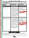
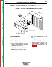
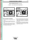
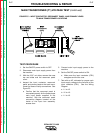
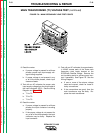
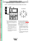
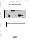
FIGURE F.3 – INPUT CONTACTOR CONNECTIONS
X1, #232
#233
TEST PROCEDURE
1. Disconnect the main input supply power to
the machine.
2. With the 5/16” nut driver, remove the case
top and the reconnect panel cover.
3. Locate the two leads connected to the input
contactor coil, #233 and X1 #232 (top). See
Figure F.3 for location.
4. Connect an AC voltmeter to the leads.
Electric Shock can kill.
• With the input power on, there
are high voltages inside the
machine. Do not reach into
the machine or touch any
internal part of the machine
while the power is on.
5. Apply the correct voltage to the machine and
turn the power switch (S1) ON.
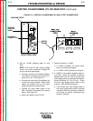
6. Check for 120VAC at the contactor coil leads.
If the 120VAC is NOT present, with the power
switch (S1) on, check the power switch (S1)
and associated circuitry. See the Wiring
Diagram. Also perform the Control
Transformer (T2) Voltage Test.
If the 120VAC is present and the contactor
does NOT activate, then the input contactor is
faulty. Replace the input contactor.
WARNING