


Return to Section TOC Return to Section TOC Return to Section TOC Return to Section TOC
Return to Master TOC Return to Master TOC Return to Master TOC Return to Master TOC
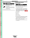
INPUT LINE VOLTAGE, CONTACTOR
AND MAIN TRANSFORMER
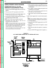
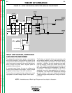
The desired three-phase input power is connected to
the CV-400 through an input contactor, located in the
input box at the rear of the machine. Two phases of the
input line are also connected to the control transformer,
which, through the power switch, supplies power to
activate the input contactor.
A reconnect panel allows the user to configure the
machine for the desired input voltage. This AC voltage
is applied to the primary of the main transformer.
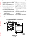
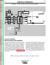
The transformer changes the high voltage, low current
input power to a lower voltage, higher current output.
The finishes or "neutrals" of the main secondary coils
are connected together, and the three starts of the sec-
ondary windings are connected to the rectifier bridge
assembly. In addition, the main transformer has sepa-
rate and isolated 115VAC and 42VAC auxiliary wind-
ings. The 115VAC is available at the terminal strip and
the 14 pin amphenol and is protected by a 10 amp cir-
cuit breaker. The 42VAC is available at the 14 pin
amphenol only and is also protected by a 10 amp cir-
cuit breaker. The three 21VAC phase angle windings
are also housed in the main transformer assembly.
These windings provide power and "timing" for the con-
trol board.
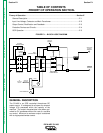
THEORY OF OPERATION
E-2 E-2
IDEALARC CV-400
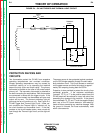
NOTE: Unshaded areas of Block Logic Diagram are the subject of discussion.
FIGURE E.2 – INPUT LINE VOLTAGE, CONTACTOR AND MAIN TRANSFORMER
FAN
115VAC
42VAC
REMOTE
CONTROL
TO
CONTROL
BOARD
CONTROL BOARD
OUTPUT
CONTROL
CONTROL
TRANSFORMER
POWER
SWITCH
R
E
C
O
N
N
E
C
T
INPUT
CONTACTOR
T
E
R
M
I
N
A
L
S
T
R
I
P
TRANSFORMER
MAIN
SCR DIODE
HYBRID BRIDGE
/
CAPACITORS
SHUNT
NEGATIVE
OUTPUT
TERMINAL
POSITIVE
OUTPUT
TERMINAL
OUTPUT
G
A
T
E
S
I
G
N
A
L
S
F
E
E
D
B
A
C
K
s
F
E
E
D
B
A
C
K
14 PIN AMPHENOL