


Return to Section TOC Return to Section TOC Return to Section TOC Return to Section TOC
Return to Master TOC Return to Master TOC Return to Master TOC Return to Master TOC
TROUBLESHOOTING & REPAIR
F-19 F-19
IDEALARC CV-400
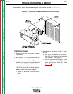
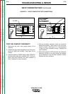
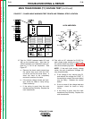
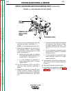
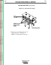
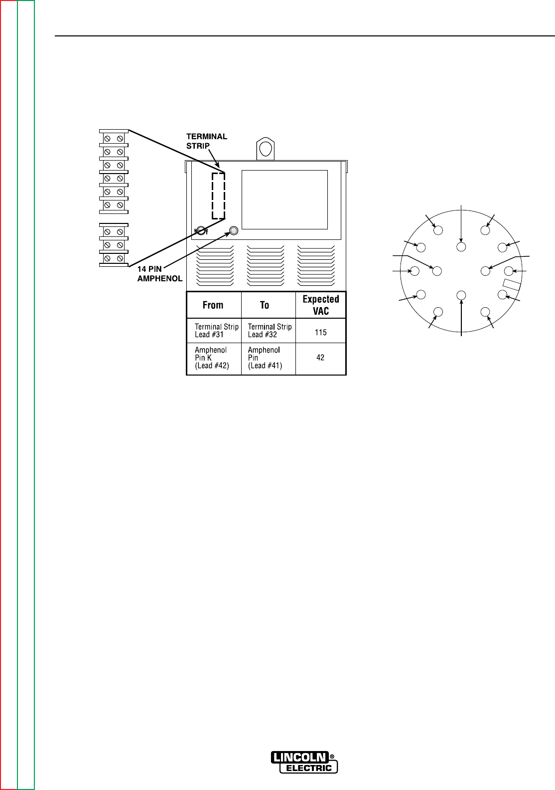
12. Test for 115VAC between leads #31 and
#32 on the terminal strip. Also test for
42VAC between pin K (lead #42) and pin I
(lead 41) in the 14-pin amphenol. See
Figure F.7.
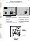
a. Remove the sheet metal screws from
the control box cover with the 5/16”
nut driver and flip the cover down. It
does not have to be completely
removed to perform the tests.
b. If the above voltage checks are incor-
rect, check for loose or faulty wiring.
Check continuity.
c. If the wiring is good, then the main
transformer may be faulty. Replace the
main transformer.
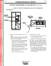
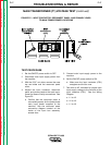
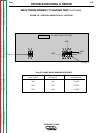
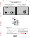
13. Test with an AC voltmeter for 21VAC for
each phase angle winding at plug P1 on
the control board as shown in Figure F.8
and the accompanying table.
NOTE: If the main input supply voltage
varies, the main transformer voltages will
vary proportionately.
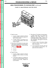
a. If the voltage is low, remove plug P1
and recheck the voltage for 21VAC. If
the reading is normal, the control board
may be faulty. Replace the control
board.
b. If one or more of the voltage tests are
incorrect, check for loose or faulty
wiring.
c. If the wiring is good, then the main
transformer may be faulty. Replace the
main transformer.
MAIN TRANSFORMER (T1) VOLTAGE TEST (continued)
FIGURE F.7 – PHASE ANGLE WINDINGS TEST POINTS AND TERMINAL STRIP LOCATION
21
4
2
BLANK
31
32
75
76
77
K=42
A=32
B=GND
L
D=4
E=77
J=31
I=41
N
G=75
F=76
M
H=21C=2
14-PIN AMPHENOL