


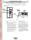
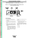
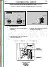

TEST FOR CONTACT CONTINUITY
1. Disconnect the main input supply power to the
machine.
2. Remove the two leads connected to the input con-
tactor coil, #233 and X1/#232. See Figure F.4 for
location.
3. Using the external 120VAC supply, apply 120VAC to
the terminals of the input contactor coil. If the con-
tactor does NOT activate, the input contactor is
faulty. Replace the input contactor.
4. With the contactor activated, check the continuity
across the contacts. (Zero ohms or very low resis-
tance is normal.) See Figure F.4. If the resistance
is high, the input contactor is faulty. Replace the
input contactor.
5. When the contactor is NOT activated, the resistance
should be infinite or very high across the contacts.
If the resistance is low, the input contactor is faulty.
Replace the input contactor.
TROUBLESHOOTING & REPAIR
F-15 F-15
IDEALARC CV-400
Return to Section TOC Return to Section TOC Return to Section TOC Return to Section TOC
Return to Master TOC Return to Master TOC Return to Master TOC Return to Master TOC
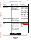
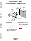
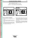
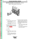
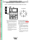
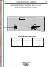
INPUT CONTACTOR TEST (continued)
FIGURE F.4 – INPUT CONTACTOR TEST CONNECTIONS
#233
APPLY EXTERNAL
120 VAC HERE
(X1, #232 AND #233
LEAD TERMINALS)
U V W
(L1) (L2) (L3)
AH# ACC730 - 8025B
(3186-30J755 18H)
LINCOLN ELECTRIC CO.
CRI SA M - 12161 - 61
LR49598 0597
X1, #232
U V W
(L1) (L2) (L3)
AH# ACC730 - 8025B
(3186-30J755 18H)
LINCOLN ELECTRIC CO.
CRI SA M - 12161 - 61
LR49598 0597