


Return to Section TOC Return to Section TOC Return to Section TOC Return to Section TOC
Return to Master TOC Return to Master TOC Return to Master TOC Return to Master TOC
TROUBLESHOOTING & REPAIR
F-6 F-6
IDEALARC CV-400
Observe Safety Guidelines TROUBLESHOOTING GUIDE
detailed in the beginning of this manual.
CAUTION
If for any reason you do not understand the test procedures or are unable to perform the test/repairs safely, con-
tact the Lincoln Electric Service Department for electrical troubleshooting assistance before you proceed. Call
216-383-2531 or 1-800-833-9353.
PROBLEMS
(SYMPTOMS)
POSSIBLE AREAS OF
MISADJUSTMENT(S)
RECOMMENDED
COURSE OF ACTION
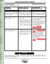
OUTPUT PROBLEMS
The machine has high welding out-
put and no control.
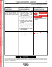
The machine has minimum (or very
low) welding output and no control.
1. If remote control is being used,
set the Output Control Switch
(S2) to the “Machine or Local”
position and control the weld
output with the machine Output
Control (R4). If the problem is
solved, check the remote con-
trol unit or wire feeder and asso-
ciated control cable.
2. Check the remote control leads
for “grounds” to the negative
welding output. If leads #75,
#76 or #77 are “grounded” to the
negative welding output, the
machine output may go very
high without control.
1. If remote control is being used,
set the Output Control Switch
(S2) to the “Machine or Local”
position and control the weld
output with the machine Output
Control (R4). If the problem is
solved, check the remote con-
trol unit or wire feeder and asso-
ciated control cable.
2. Make certain the remote control
leads (#75, #76, #77) are not
grounded to the positive welding
output.
3. Make certain the three-phase
input voltage is correct and
matches the machine rating and
the reconnect panel.
1.
Check the Output Control switch
(S2) and associated wiring. See
the Wiring Diagram.
2. Check feedback leads #220,
#204, #205 and #206 for loose
or faulty connections.
3. Perform the
SCR/Diode
Rectifier Bridge Test.
4. The control board may be
faulty. Replace.
1. Check the Output Control (R4)
and associated wiring. See the
Wiring Diagram.
2. Check the Output Control switch
(S2) and associated wiring. See
the Wiring Diagram.
3. Perform the
Main Transformer
Test.
4. Perform the
SCR/Diode Rectif-
ier Bridge Test.
5. The control board may be faulty.