


Return to Section TOC Return to Section TOC Return to Section TOC Return to Section TOC
Return to Master TOC Return to Master TOC Return to Master TOC Return to Master TOC
TROUBLESHOOTING & REPAIR
F-40 F-40
IDEALARC CV-400
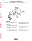
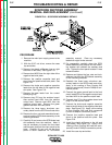
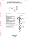
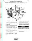
FIGURE F.21 – 1/2” WIDE LEAF SPRING
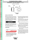
FIGURE F.22 – CLAMP ASSEMBLY
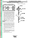
SCR REMOVAL AND REPLACEMENT (continued)
10. Go to the procedure below that matches your
machine’s cap screws. NOTE WHICH THREAD IS
ON YOUR CAP SCREWS BEFORE PROCEEDING
TO THE ASSEMBLY PROCEDURE. Two different
designs of leaf springs and housings have been
used to clamp the SCR to the rectifier. The two
different designs can be identified by the size of
the leaf spring. One design uses a 1/2 inch wide
leaf spring, and the other uses a 5/8 inch wide
spring. The different designs require different
assembly and clamping procedures. The assem-
bly procedure will be different depending upon the
thread on the cap screws. A 1/4-28 thread
requires a different tightening procedure than a
1/4-20 thread.
PROCEDURE FOR THE 1/2 INCH WIDE
SPRING
1. Place a piece of sleeving around each cap screw.
2. Insert cap screws through the leaf spring. Orient
the leaf spring so that its ends are curved upward
toward the cap screw heads. See Figure F.21.
Pressing on the cap screw heads should produce
a “rocking” motion of the spring in its housing. If
the spring does NOT rock, it is installed upside
down. Remove the spring and turn it over. Check
for “rocking” motion. See Figure F.21.
3. Insert cap screws and leaf spring into the plastic
housing.
4. Insert clamp assembly through heat sinks. Install
nuts. Tighten clamp nuts equally on cap screws
until finger tight. (See Figure F.22. Heat sinks may
not be exactly as pictured.)
5. Reinspect the SCR for proper seating.