


OVERLOAD PROTECTION
The power source is thermostatically protected with
proximity thermostats against overload or insufficient
cooling. One thermostat is located on the nose of the
center bottom primary coil and a second thermostat is
attached to the lead connecting the secondaries. Both
thermostats are connected in series with 2-4 circuit. If
the machine is overloaded, the primary thermostat will
open, the output will be zero, the amber thermal pro-
tection light will be on and the fan will continue to run.
The secondary thermostat will open either with an
excessive overload or insufficient cooling. The output
will be zero, the amber protection light will be on and
the fan will continue to run. When the thermostats
reset, the protection light will be off.
The power source is also protected against overloads
on the SCR bridge assembly through the solid state
fault protection circuit. This circuit senses an overload
on the power source and limits the output to approxi-
mately 550 amps by phasing back the SCR’s.
Protection is provided to protect the circuitry from acci-
dental grounds. If leads 75, 76, or 77 are accidentally
“grounded” to the positive output lead, the output will be
reduced to a low value, thus preventing any damage to
the machine. If the ground occurs between 75, 76, 77
and the negative output lead, one of the PC board elec-
tronic “self-restoring” fuses will blow, preventing any
machine damage. After the ground is cleared, the
fuses automatically reset within a few seconds.
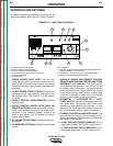
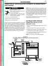
AUXILIARY POWER
On machines above code 9400, the IDEALARC CV-
400 can provide nominally 115 volts AC and 42 volts
AC auxiliary power for operating wire feeding equip-
ment and other accessories. This power is available at
the 14-pin amphenol on the control panel and/or at the
terminal strip behind the hinged control panel on the
case front. On the amphenol, 115 volts AC is available
at pins A and J (Domestic and Export models only); 42
volts AC is available at pins I and K. On the terminal
strip, 115 volts AC is available at terminals 31 and 32;
42 volts AC is not available at the terminal strip. The
two circuits, 115 volts AC and 42 volts AC, are isolated;
and each is protected by a 10 amp circuit breaker.
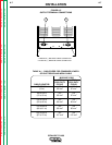
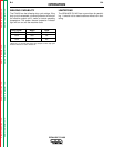
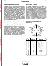
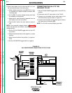
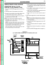
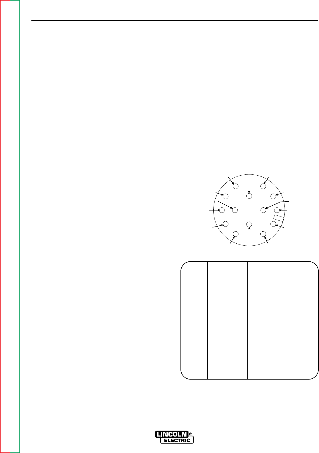
FRONT VIEW OF 14-PIN CONNECTOR
RECEPTACLE
OPERATION
B-7 B-7
IDEALARC CV-400
Return to Section TOC Return to Section TOC Return to Section TOC Return to Section TOC
Return to Master TOC Return to Master TOC Return to Master TOC Return to Master TOC
K=42
A=32
B=GND
L
D=4
E=77
J=31
I=41
N
G=75
F=76
M
H=21C=2
PIN LEAD NO. FUNCTION
A 32 115 VAC
B GND Chassis Connection
C 2 Trigger Circuit
D 4 Trigger Circuit
E 77 Output Control
F 76 Output Control
G 75 Output Control
H 21 Work Connection
I 41 42 VAC
J 31 115 VAC
K 42 42 VAC
L --- ---
M --- ---
N --- ---