


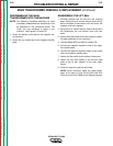

REASSEMBLING THE MAIN
TRANSFORMER INTO THE MACHINE
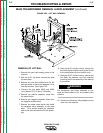
NOTE: The following procedure assumes you have
completely reassembled the transformer coils
as described in the procedure above. The
lower iron has remained in place in the
machine. See Figures F.25 and F.26.
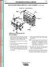
1. Attach the bottom choke lead to the negative out-
put terminal.
2. Attach the top choke lead to the negative rectifier
plate.
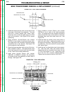
REASSEMBLE THE LIFT BAIL
1. Carefully position the lift bail onto the machine
base. Using the 9/16” socket wrench, attach the lift
bail to the base of the machine with four bolts, flat
washers, and lock washers.
2. Using the 9/16” socket wrench, attach the lift bail to
the transformer top and bottom irons with four
bolts.
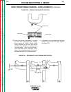
3. Attach the sheet metal screw that holds the capac-
itor bank assembly to the case back.
4. Connect leads #220 and #204 to resistor R2.
5. Connect the negative capacitor strap to the nega-
tive rectifier plate.
6. Connect the positive capacitor strap to the output
shunt and positive rectifier plate.
7. Attach the fiber baffle on the bottom choke lead.
8. Attach the two fiber baffles to the left and right
sides of the lift bail, adjacent to the main trans-
former.
9. Install the machine case top and sides.
NOTE: When aluminum leads are reconnected,
apply a thin layer of Dow Corning 340 Heat Sink
Compound (Lincoln E1868) to the mating surfaces.
TROUBLESHOOTING & REPAIR
F-52 F-52
IDEALARC CV-400
Return to Section TOC Return to Section TOC Return to Section TOC Return to Section TOC
Return to Master TOC Return to Master TOC Return to Master TOC Return to Master TOC
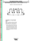
MAIN TRANSFORMER REMOVAL & REPLACEMENT (continued)