


Return to Section TOC Return to Section TOC Return to Section TOC Return to Section TOC
Return to Master TOC Return to Master TOC Return to Master TOC Return to Master TOC
TROUBLESHOOTING & REPAIR
F-51 F-51
IDEALARC CV-400
MAIN TRANSFORMER REMOVAL & REPLACEMENT (continued)
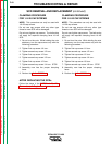
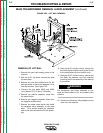
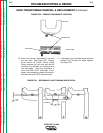
10. Mount the primary thermostat to the lead
end coil nose. See Figure F.30. Place a
small amount of Lincoln Electric E1603
Epoxy between the coil nose and the coil
insulation and between the insulation and
the thermostat. Hold the thermostat in
place with E2381 (.375” wide) tape. If nec-
essary, after assembly protect the thermo-
stat terminals with E2547 terminal boots.
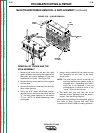
11. If necessary, trim off excess secondary lead
stickout and TIG weld the leads together.
See Figure F.31.
FIGURE F.30 – PRIMARY THERMOSTAT LOCATION
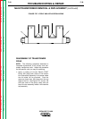
FIGURE F.31 – SECONDARY LEAD TRIM AND WELD DETAIL
TIG WELD
TOP VIEW
THERMOSTAT
FRONT VIEW
INSULATION