


Have a qualified electrician connect the input power
leads to the L1, L2, and L3 terminals of the input con-
tactor. Follow all national and local electrical codes.
Use a three-phase line. Install the reconnect panel
jumper links (see Figure A.3) for the proper input volt-
age. See the connection diagram located on the inside
cover of the access panel cover. Also refer to
Reconnect Procedure
later in this section.
INPUT WIRE AND FUSE SIZE
Fuse the input circuit with the super lag fuse recom-
mended in the
Technical Specifications
at the begin-
ning of this section or use delay type
1
circuit breakers.
Choose an input and grounding wire size according to
local or national codes; also see the
Technical
Specifications
. Using fuses or circuit breakers smaller
than recommended may result in "nuisance" shut-offs
from welder inrush currents, even if you are not weld-
ing at high output currents.
1
Also called "inverse time" or "thermal/magnetic" circuit breakers.
These circuit breakers trip faster as the magnetude of the fault cur-
rent increases.
INSTALLATION
A-5 A-5
IDEALARC CV-400
Return to Section TOC Return to Section TOC Return to Section TOC Return to Section TOC
Return to Master TOC Return to Master TOC Return to Master TOC Return to Master TOC
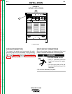
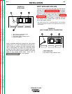
1. INPUT SUPPLY LINE ENTRY HOLE
2. INPUT CONTACTOR CR1
3. RECONNECT PANEL/JUMPER LINKS
4. GROUND TERMINAL
FIGURE A.2
REAR PANEL
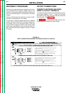
FIGURE A.3
INPUT POWER SUPPLY CONNECTIONS
1. INPUT SUPPLY LINE
2. INPUT CONTACTOR
3. RECONNECT PANEL/JUMPER LINKS