


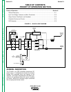

THEORY OF OPERATION
E-3 E-3
IDEALARC CV-400
Return to Section TOC Return to Section TOC Return to Section TOC Return to Section TOC
Return to Master TOC Return to Master TOC Return to Master TOC Return to Master TOC
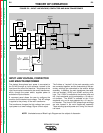
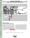
OUTPUT CONTROL,
RECTIFICATION AND FEEDBACK
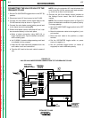
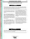
The three-phase AC output from the main transformer
secondary is rectified and controlled through the
SCR/diode bridge. Output current and voltage is
sensed at the shunt and output capacitors, respective-
ly. This feedback information is processed in the con-
trol board. The control board compares the commands
of the output control (or remote control) with the feed-
back information and sends the appropriate gate firing
signals to the SCR/diode bridge.
See SCR Operation
in this section.
A "dry closure" of leads #2 and #4, either at the termi-
nal strip or the 14 pin amphenol, signals the control
board to apply gate firing signals to the SCR/diode
bridge, which creates a DC voltage at the output of
the bridge assembly. This output is filtered by the
capacitors to reduce the ripple content of the wave-
form. Thus, a smoother DC output is created. The
choke, which is in series with the negative output ter-
minal, stores energy and provides current filtering.
NOTE: Unshaded areas of Block Logic Diagram are the subject of discussion.
FIGURE E.3 – OUTPUT CONTROL, RECTIFICATION AND FEEDBACK
FAN
115VAC
42VAC
REMOTE
CONTROL
TO
CONTROL
BOARD
CONTROL BOARD
OUTPUT
CONTROL
CONTROL
TRANSFORMER
POWER
SWITCH
R
E
C
O
N
N
E
C
T
INPUT
CONTACTOR
T
E
R
M
I
N
A
L
S
T
R
I
P
TRANSFORMER
MAIN
SCR DIODE
HYBRID BRIDGE
/
CAPACITORS
SHUNT
NEGATIVE
OUTPUT
TERMINAL
POSITIVE
OUTPUT
TERMINAL
OUTPUT
G
A
T
E
S
I
G
N
A
L
S
F
E
E
D
B
A
C
K
s
F
E
E
D
B
A
C
K
14 PIN AMPHENOL