


Return to Section TOC Return to Section TOC Return to Section TOC Return to Section TOC
Return to Master TOC Return to Master TOC Return to Master TOC Return to Master TOC
OPERATION
B-6 B-6
IDEALARC CV-400
WELDING OPERATION
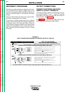
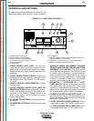
LOCAL CONTROL
The following procedures are for using the CV-400 in
the local control mode of operation. For remote control
of the machine, see the Remote Control section.
Before operating the machine, make sure you have all
materials needed to complete the job. Be sure you are
familiar with and have taken all possible safety precau-
tions before starting work. It is important that you follow
these operating steps each time you use the machine.
1. Turn on the main AC input power to the machine.
2. Set the VOLTMETER "+" or "-" switch to the appro-
priate position.
- Set toggle to " Electrode Negative" position if the
electrode is connected to the negative (-) output ter-
minal.
- Set toggle to "Electrode Positive" position if the elec-
trode is connected to the positive (+) output terminal.
3. Set the OUTPUT CONTROL switch to "Local."
(Exception: when using an LN-9, LN-9 GMA, or NA-
5 wire feeder, set the switch to "Remote." Otherwise,
the wire feeder may automatically shut down.)
4. Set the ON/OFF switch to the ON position (I). The
power source pilot light glows and the fan starts.
5. Set the OUTPUT CONTROL Potentiometer to the
desired voltage.
6. Make the weld.
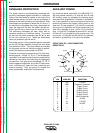
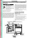
REMOTE CONTROL
The toggle switch on the control panel labeled "Output
Control Remote" gives you the option of controlling the
machine output from a remote location. In the
"Remote" position a wire feeder with remote control
capabilities or a remote control device such as a K775
must be connected to the CV-400. See the
Accessories
section for wire feeder installation infor-
mation.